
LEDMall Blog
NovaStar A10s Plus vs A10s Pro: Revision and Compatibility Guide
Nov
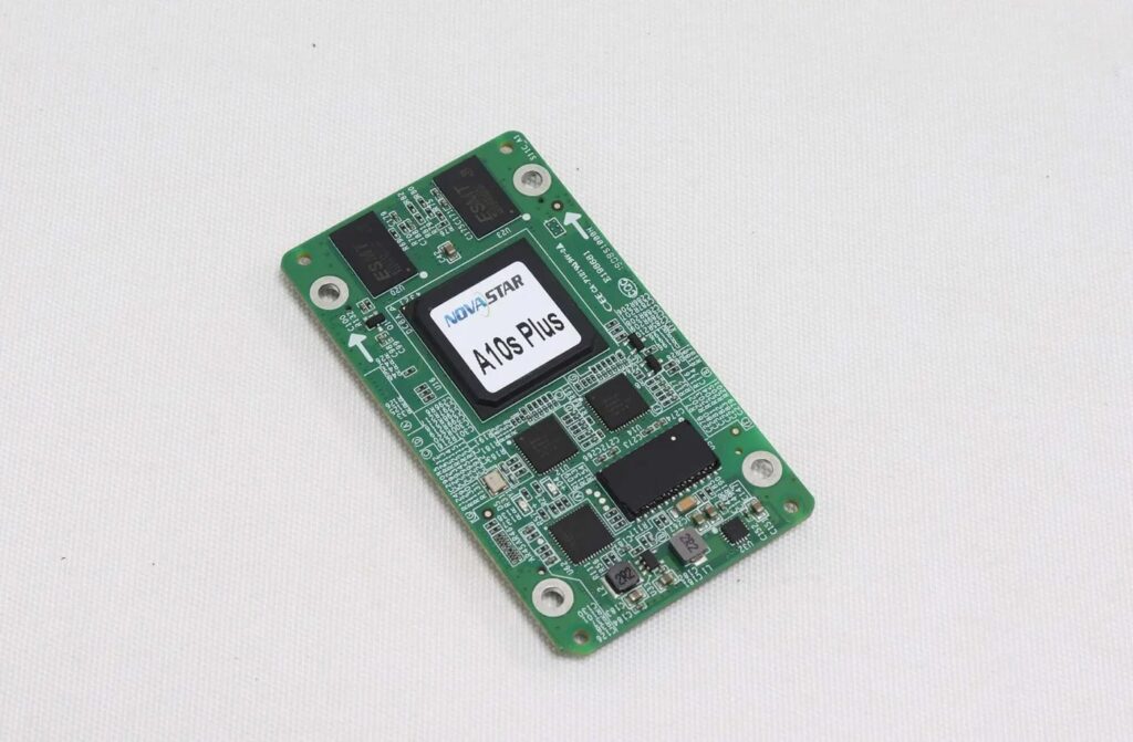
An A10s Plus vs A10s Pro choice depends on the exact cabinet, required image functions and supported controller combination. Both families use compact high-density connections, but a shared nominal pixel capacity does not establish that they are interchangeable. The Pro documents additional calibration functions, while electrical and mechanical parameters must be checked against the supplied revision.
This guide is for AV integrators specifying receiving cards for a cabinet build or a planned hardware change. It compares the evidence needed for selection, rather than treating the Pro suffix as automatic approval for an existing screen.
Keep A10s Plus, A10s Plus-N and A10s Pro distinct. This article compares the A10s Plus and A10s Pro listings on LED Mall. A document for another suffix is not a substitute for identifying the board being supplied.
1. Identify the Exact Boards in an A10s Plus vs A10s Pro Review
Start with full model labels, hardware information and the relevant specification revision. This prevents a comparison from combining a convenient figure from one document with a feature from another.
01. Keep document and hardware identity together
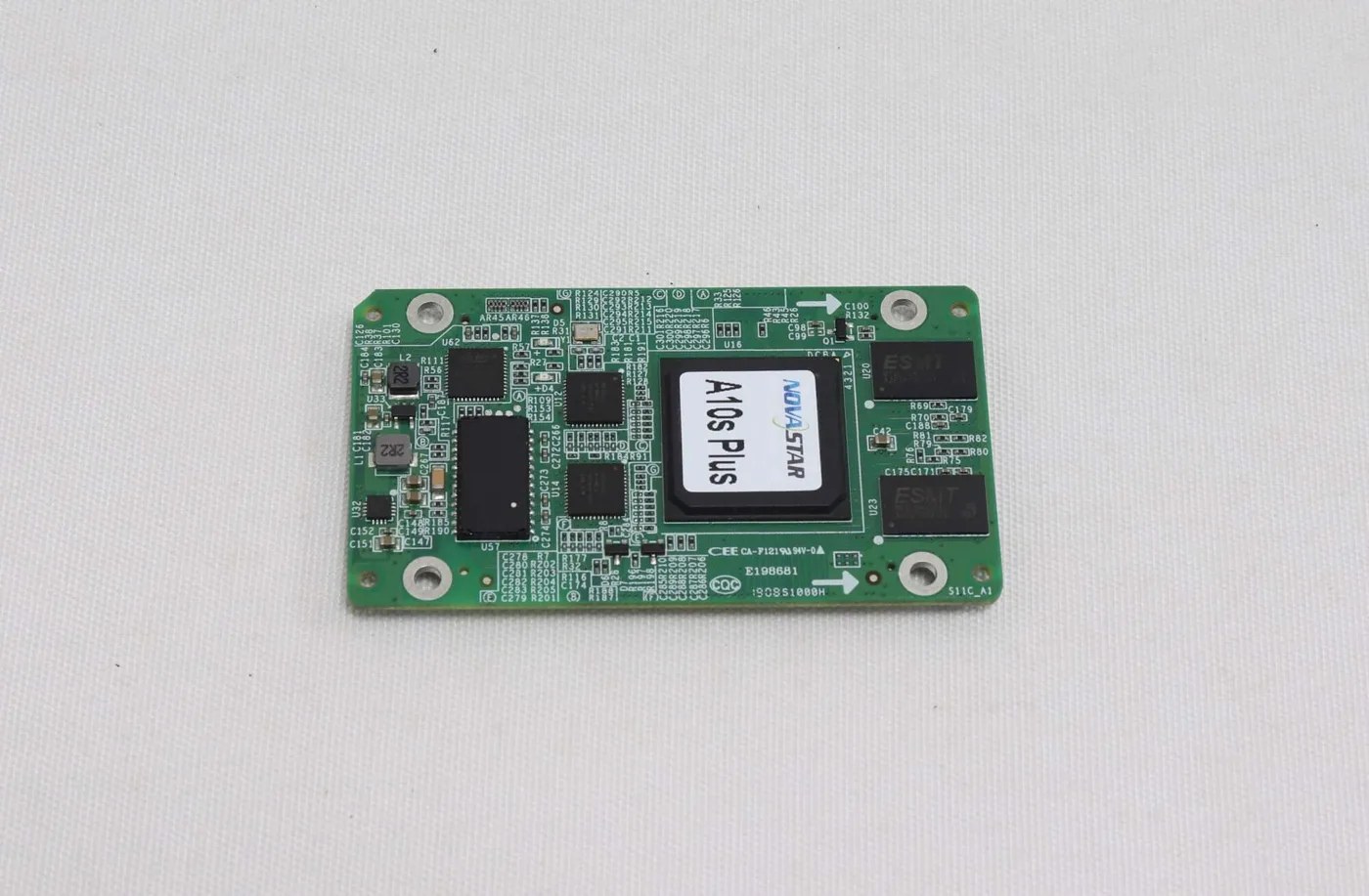
The A10s Plus product page distinguishes its own V1.0.0 and V1.0.3 parameters from a retained download that opens an A10s Pro document. That download should not be used to infer the Plus board’s dimensions, supply requirements or functions.
The A10s Pro page also preserves an older specification while explaining changes in a later document. A version number on a specification identifies a document, not necessarily the hardware or firmware installed in a cabinet. Record both where the information is available.
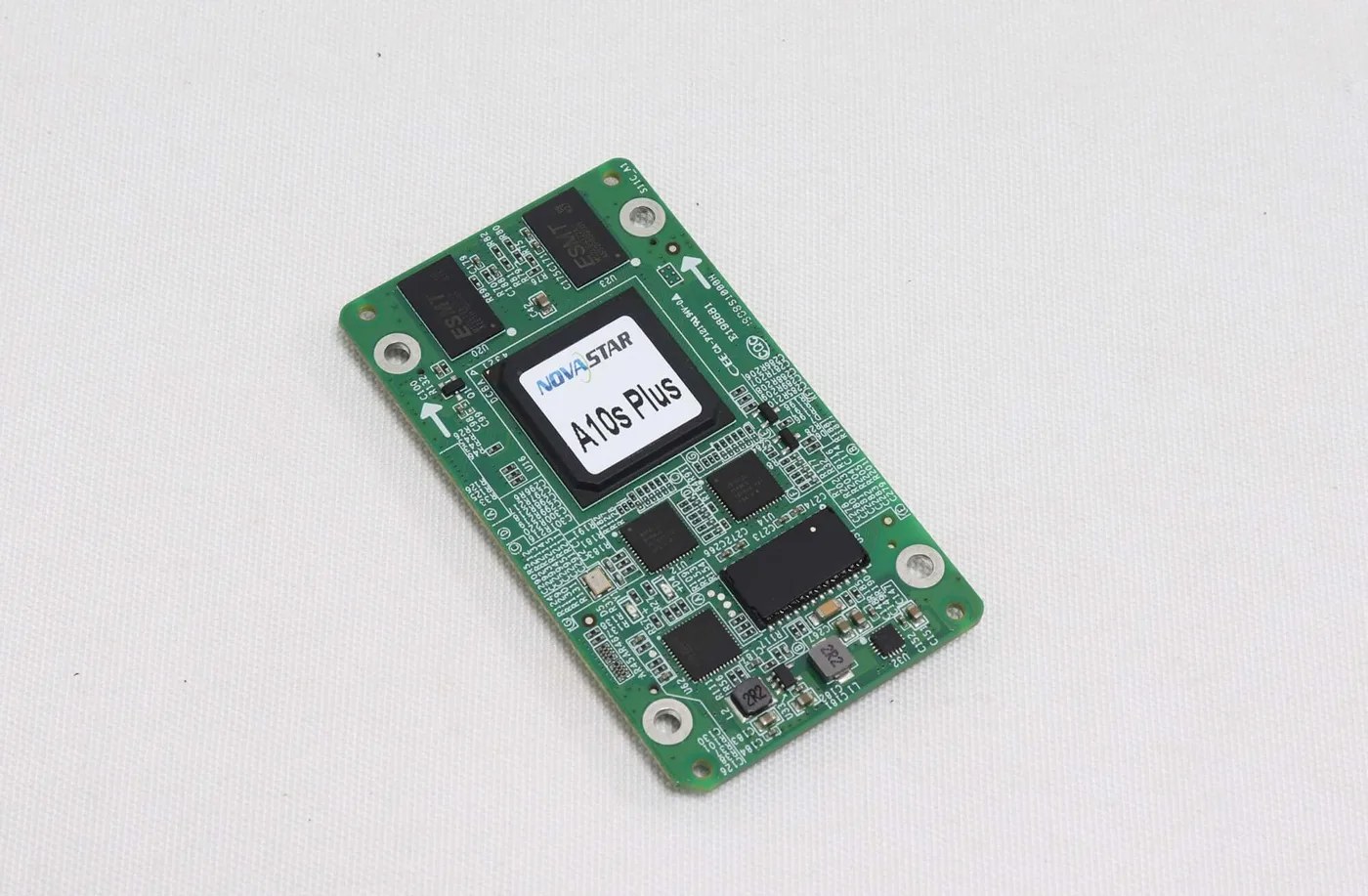
For A10s Plus vs A10s Pro procurement, ask the supplier to identify the proposed model and the specification that applies to the supplied unit. Keep that response with the cabinet build record. A clear model photograph is more useful than an abbreviated purchase line saying only A10s.
02. Define the purpose of the change
A new cabinet design, a like-for-like repair and a display-quality upgrade are different projects. The first needs a reviewed bill of materials. The second needs preservation of the existing working configuration. The third needs a measurable image requirement and confirmation that the complete chain can support it.
Write the intended result in plain terms: for example, correcting a failed cabinet, retaining calibration after service, or supporting a specified HDR workflow. Do not replace that requirement with a request for the highest model in the range.
2. Compare the Functions That Matter to the Cabinet
The meaningful A10s Plus vs A10s Pro distinction is the supported function in the intended system. Similar connector architecture and data-group counts do not prove identical behavior.
| Question | A10s Plus reference | A10s Pro reference | Selection condition |
|---|---|---|---|
| Nominal pixel loading | Up to 512 × 512 pixels in retained Plus documents | Up to 512 × 512 at 60 Hz; later document distinguishes source bit depth and PWM drivers | Confirm the actual module, source format and operating settings |
| Output arrangement | Up to 32 parallel groups or 64 serial groups | Up to 32 parallel RGB or 64 serial groups | Match HUB routing and module data layout |
| Calibration emphasis | Pixel-level brightness/chroma calibration and revision-dependent Image Booster description | Full-Grayscale Calibration, Dynamic Booster and Image Booster | Verify supporting controller, software, firmware and driver IC |
| HDR | HDR10 and HLG with a supporting controller; older document names MCTRL4K | HDR10 and HLG with a supporting sender able to parse the source | Validate the entire HDR signal path |
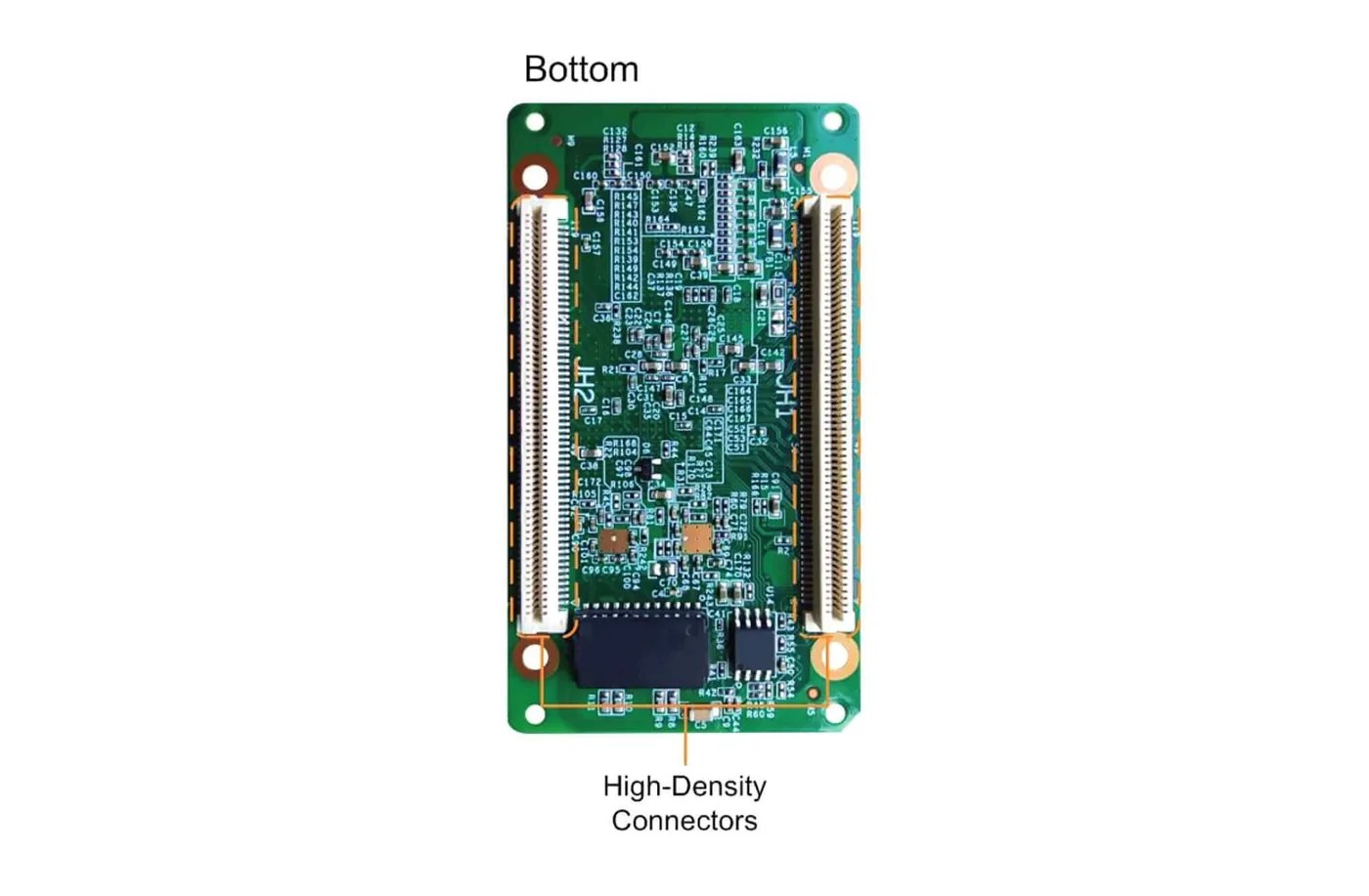
| Physical integration | High-density connector arrangement; 80 × 45 mm footprint | High-density connector arrangement; 80 × 45 mm footprint | Check mating connectors, height, pinout and mounting clearance |
Review the A10s Plus model notes and A10s Pro specifications alongside this table. It is a shortlist aid, not a substitution chart.
In A10s Plus vs A10s Pro discussions, identify which listed feature is actually required by the job. If the system will not use the relevant calibration workflow or compatible controller, a feature name alone does not establish a visible benefit for that installation.
3. Check Loading Conditions Instead of Comparing One Number
Card loading depends on the documented operating conditions. Keep width, height, frame rate, source bit depth and module driver information together when checking a cabinet.
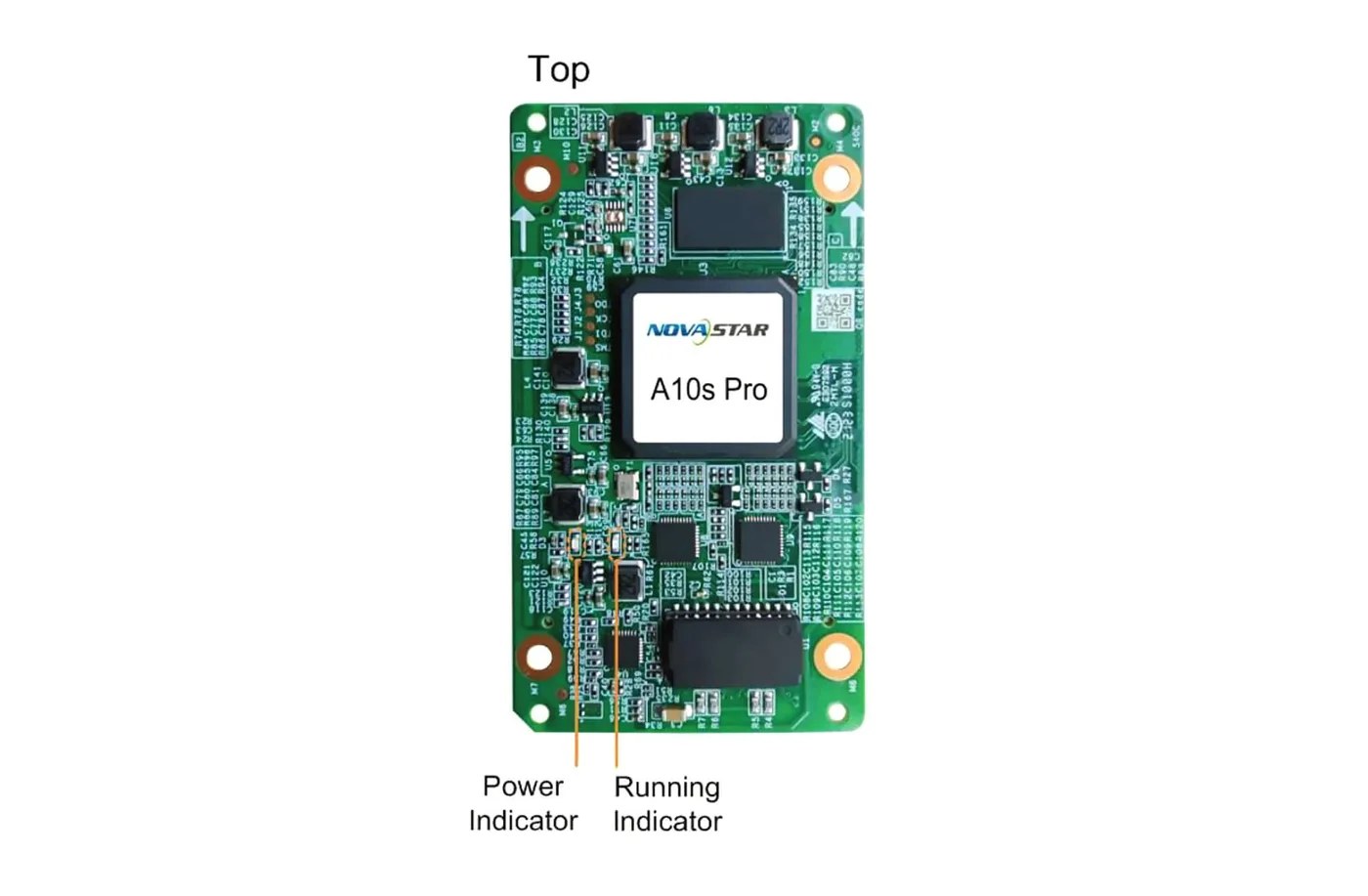
The A10s Pro product page cites V1.3.0, dated August 20, 2024, for a distinction that matters in a high-bit-depth design: up to 512 × 512 at 60 Hz for 8-bit and 10-bit sources with PWM driver ICs, and 512 × 256 at 60 Hz for 12-bit sources. Do not silently apply the larger dimensions to the 12-bit case.
Consider a hypothetical 384 × 384-pixel cabinet. It contains 147,456 pixels. Its 384-pixel height exceeds a 256-pixel height limit, and its total also exceeds 131,072 pixels. The cabinet therefore cannot be qualified against that stated 12-bit loading envelope by quoting a different operating mode.
For a second hypothetical cabinet, 512 × 192 gives 98,304 pixels. That is within the stated 512 × 256 dimensions as a numerical screening check. It still does not validate the HUB board, driver IC, data groups or firmware. Mathematical headroom is a first filter, not proof of cabinet compatibility.
An A10s Plus vs A10s Pro evaluation should ask for the exact mode required by the project. Do not turn a receiver’s 60 Hz loading figure into an LED panel refresh-rate claim. Frame rate, module refresh behavior and grayscale processing are different parameters.
Also record whether 3D, rotation or another special function is required. A table of ordinary two-dimensional capacity should not be reused for a different processing mode unless the applicable manufacturer document confirms the conditions.
4. Keep Electrical and Mechanical Revisions Separate
A10s Plus vs A10s Pro comparisons become unreliable when older and newer electrical figures are mixed. Select the applicable revision before sizing the power connection or approving clearance.
| Model and document | Input and rated consumption | Dimensions | Action |
|---|---|---|---|
| A10s Plus V1.0.0 | DC 3.3–5.5 V; 0.5 A; 2.5 W | 80.0 × 45.0 × 7.3 mm | Check the supplied board rather than assuming this is the only height |
| A10s Plus V1.0.3 | Use the applicable full specification | 80.0 × 45.0 × 7.9 mm | Keep the later mechanical value tied to this document |
| A10s Pro V1.1.2 | DC 3.3–5.5 V; 0.5 A; 2.5 W | 80.0 × 45.0 × 8.0 mm | Do not use the older current value for a later unit without confirmation |
| A10s Pro V1.3.0 | DC 3.8–5.5 V; 0.8 A; 4.0 W | 80.0 × 45.0 × 8.6 mm | Confirm this specification applies to the hardware being supplied |
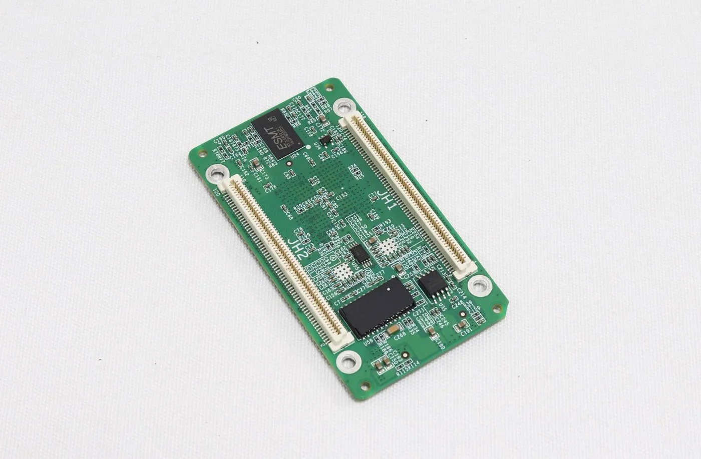
The shared 80 × 45 mm footprint is approximately 3.15 × 1.77 in. That footprint says nothing about connector mating height, component clearance or the cabinet’s power connector. Use the full mechanical drawing, pin definitions and actual mating board during the integration review.
Have a qualified technician isolate the cabinet before moving a card or checking internal connections. Preserve polarity and the approved wiring arrangement. A compatible supply-voltage range does not make an unknown pinout safe to try.
If the cabinet has limited clearance, obtain a photograph and measurement of the mating assembly. The card can fit within the nominal board footprint while still conflicting with a cable, standoff or nearby component. Include those constraints in the order request.
5. Define the Image Function and Its Dependencies
The Pro’s documented calibration capabilities must be evaluated as part of the supported control and module system. A card change alone is not evidence of better contrast, uniformity or grayscale performance.
01. Distinguish calibration from a feature label
Full-Grayscale Calibration assigns calibration coefficients across source grayscale levels. That differs from simply stating that a card supports brightness adjustment. Ask how the project’s calibration data will be created, stored and restored, and which supporting equipment or software the process requires.
The A10s Pro page describes Dynamic Booster and Image Booster, while warning that the actual Image Booster result depends on the driver IC. Its cited requirement is NovaLCT V5.4.0 or later. The Plus V1.0.3 description identifies Image Booster with NovaLCT V5.3.1 or later. These references should not be reduced to one universal software requirement for both boards.
In an A10s Plus vs A10s Pro upgrade proposal, request a demonstration or an acceptance criterion appropriate to the actual screen. Do not present an unmeasured energy-saving percentage or image improvement as an expected result for every cabinet.
02. Keep HDR, rotation and latency conditions attached
HDR requires a supporting sender or controller and an appropriate source path. Confirm the full route from source format through controller processing to the receiver and module. Writing HDR next to the receiving-card model does not establish that the existing controller can parse the source.
The retained descriptions distinguish rotation in 90-degree steps from arbitrary-angle rotation. The latter requires SmartLCT and MCTRL R5 in the documented arrangement. State the angle and software workflow needed by the project instead of asking only whether rotation is supported.
The cited one-frame receiving-card latency requires modules using driver ICs with built-in RAM. It is not a complete source-to-screen latency measurement. If live performance or camera timing is important, define the entire chain and test the intended operating conditions.
6. Plan Configuration, Calibration and Service Files
Before changing receiver hardware, preserve the existing approved configuration, mapping and calibration records. These records describe different parts of the display and should remain identifiable after the repair or upgrade.
A receiving-card configuration establishes how the installed module arrangement is driven. Screen mapping identifies where cabinet images belong in the wall. Calibration records address the display’s adjustment data. Copying one file should not be assumed to reproduce all three.
Label each file with the cabinet type, original card identity, relevant software or firmware information and the date of the approved setup. Keep a copy separate from the laptop used for commissioning. A working cabinet can be a useful reference only when its module arrangement and hardware are verified to match.
For A10s Plus vs A10s Pro validation, begin with a single matching cabinet and an isolated or carefully targeted configuration procedure. Check full module coverage, orientation, colors, mapped content and retention after a controlled restart. Then evaluate the required calibration or special functions.
Where a suitable HUB board supports dual-card backup, document that board and the required connections. Loop backup, stored programs and stored calibration data are different recovery functions. Specify the failure each proposed backup is intended to address.
Read the general receiving-card replacement guide for fault-isolation and identification steps. This article adds the model and revision questions needed for these two compact receivers; it does not replace the cabinet’s approved service procedure.
Acceptance should include a normal restart and an operator handover. Record which configuration was saved, where the approved files are stored and what was actually tested. If the required image function cannot be demonstrated in the proposed system, keep it as an unresolved requirement instead of a purchase assumption.
7. Keep a Revision-Specific Decision Record
An A10s Plus vs A10s Pro decision is easier to review when the required result and the evidence for each condition appear in the same record. Keep unresolved items visible rather than replacing them with a broad compatibility statement.
For a new cabinet, begin with the module supplier’s information. Identify driver IC, scan arrangement, module pixels and the approved data path. Add the proposed receiver and HUB board only after those requirements are known. This prevents a convenient receiver stock item from defining an unsupported module design.
For a service replacement, begin with the installed cabinet. Record the original model, photographs, mating board and known working settings. A purchasing team can then ask for an exact-model spare or a specifically reviewed alternative, without suggesting that every card sharing the board footprint is equivalent.
For a quality-related upgrade, identify the content and observation that motivate it. A requirement involving dark tones should describe the intended content and the acceptance method. A requirement involving live timing should identify the source chain and operating mode. Avoid a vague request for a more powerful board.
Keep the image-function dependency beside the proposed part. For example, if Full-Grayscale Calibration is the reason to consider Pro, confirm the supporting control and calibration workflow. If the requirement is HDR, confirm the source and sender path as well as the receiver. Neither requirement is resolved by a card label alone.
The electrical review should quote the applicable input range and current or power information from one identified document. Do not select a lower current from an older reference because it is convenient for the existing supply arrangement. Have the actual cabinet power connection reviewed against the supplied hardware.
The mechanical review should name the mating HUB assembly and check the maximum occupied height. A drawing that includes only the bare board length and width leaves a clearance question unanswered. Photograph the assembled connectors and nearby components if the installation has little room.
Record the expected commissioning work in the purchasing discussion. A compatible alternative may still require approved configuration, calibration handling and validation. Those are real project tasks, even when the replacement board can be physically installed without changing the cabinet structure.
Use a simple status for each requirement: confirmed with evidence, needs confirmation, or not required by this project. This is more informative than marking the whole proposal compatible before the module or controller has been identified. It also gives the supplier a specific question to answer.
After the cabinet test, replace open assumptions with the observed result and the final approved files. Record which source bit depth, frame rate and module arrangement were actually used. A successful test under one condition should not be rewritten as approval for an untested higher-bit-depth mode.
Retain the original files when the new setup is accepted, with clear labels distinguishing the old and new arrangements. The record should support later service without encouraging an operator to apply an outdated file to a changed cabinet.
This approach keeps the A10s Plus vs A10s Pro comparison useful after purchasing. It explains why the part was selected, which revision was reviewed and what work remains necessary before the cabinet can return to normal operation.
Frequently Asked Questions
Can I mix Plus and Pro cards across one wall?
Do not assume that mixed cards will provide identical behavior. Review the controller, modules, configuration, calibration and required functions for the complete wall. A single working cabinet does not establish uniform operation across a mixed installation.
Does the A10s Pro document linked from the Plus page prove Plus compatibility?
No. The Plus listing explicitly identifies that retained download as a different-model reference. Use the Plus specifications and the supplied board identity for Plus parameters.
Is A10s Plus-N the same comparison?
No. Keep the full suffix in the request. This A10s Plus vs A10s Pro article does not establish the behavior of a Plus-N board. Obtain the correct specification if that is the model installed or offered.
Will calibration records transfer automatically?
Confirm the documented storage and restoration arrangement. Some module-flash functions require modules with flash memory, and other functions depend on the applicable firmware. Preserve the original records before any change.
Should I update firmware before checking a new card?
Identify the supplied firmware and approved cabinet requirements first. Do not apply an unrelated update simply to make model names or version strings look alike. Obtain the appropriate package and procedure for the exact board and module configuration.
Request a Cabinet-Specific Card Review
If the cabinet uses direct HUB75E module connections, review the DH receiving-card comparison before assuming a compact-card arrangement. Use the MCTRL sending-controller guide to define the upstream signal requirements separately.
For an A10s Plus vs A10s Pro inquiry, send the existing board label, HUB photographs, module driver IC, cabinet pixels and controller model. Add the source bit depth and the calibration, HDR or rotation function required. Ask LED Mall to confirm the proposed receiver and revision before ordering or scheduling a cabinet change.