
LEDMall Blog
NovaStar DH7512-S vs DH7516-S: HUB75E and Cabinet Selection
Nov
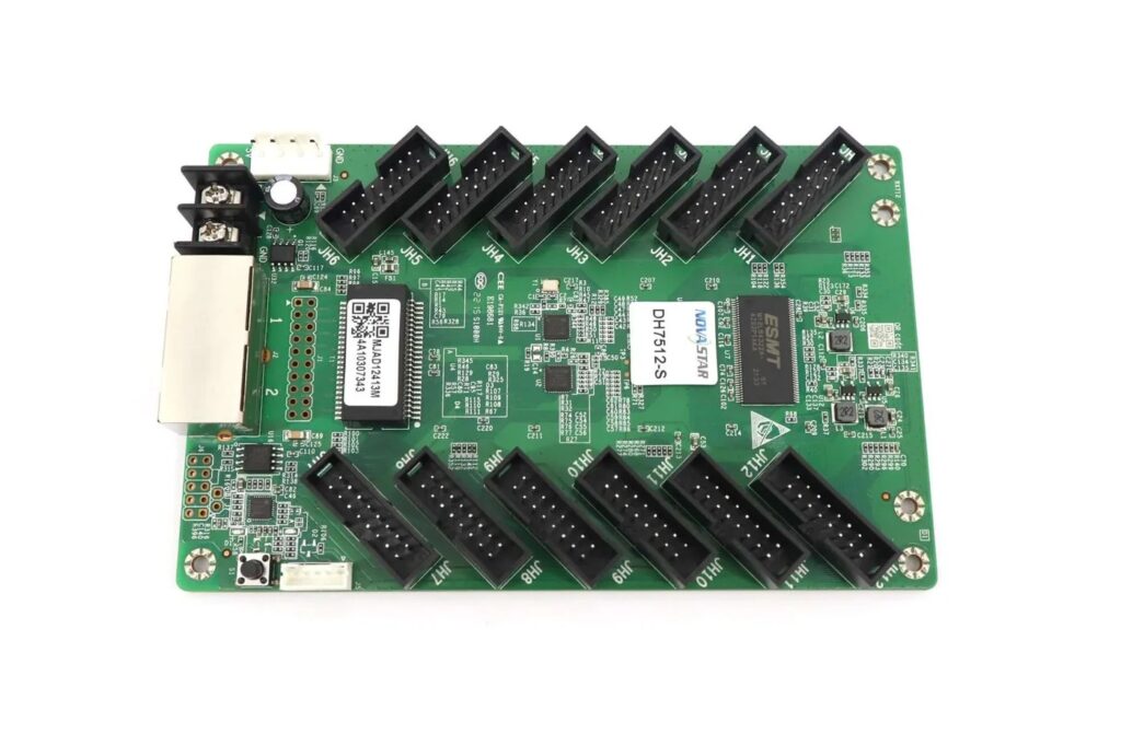
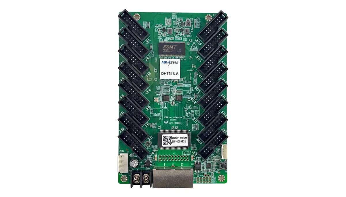
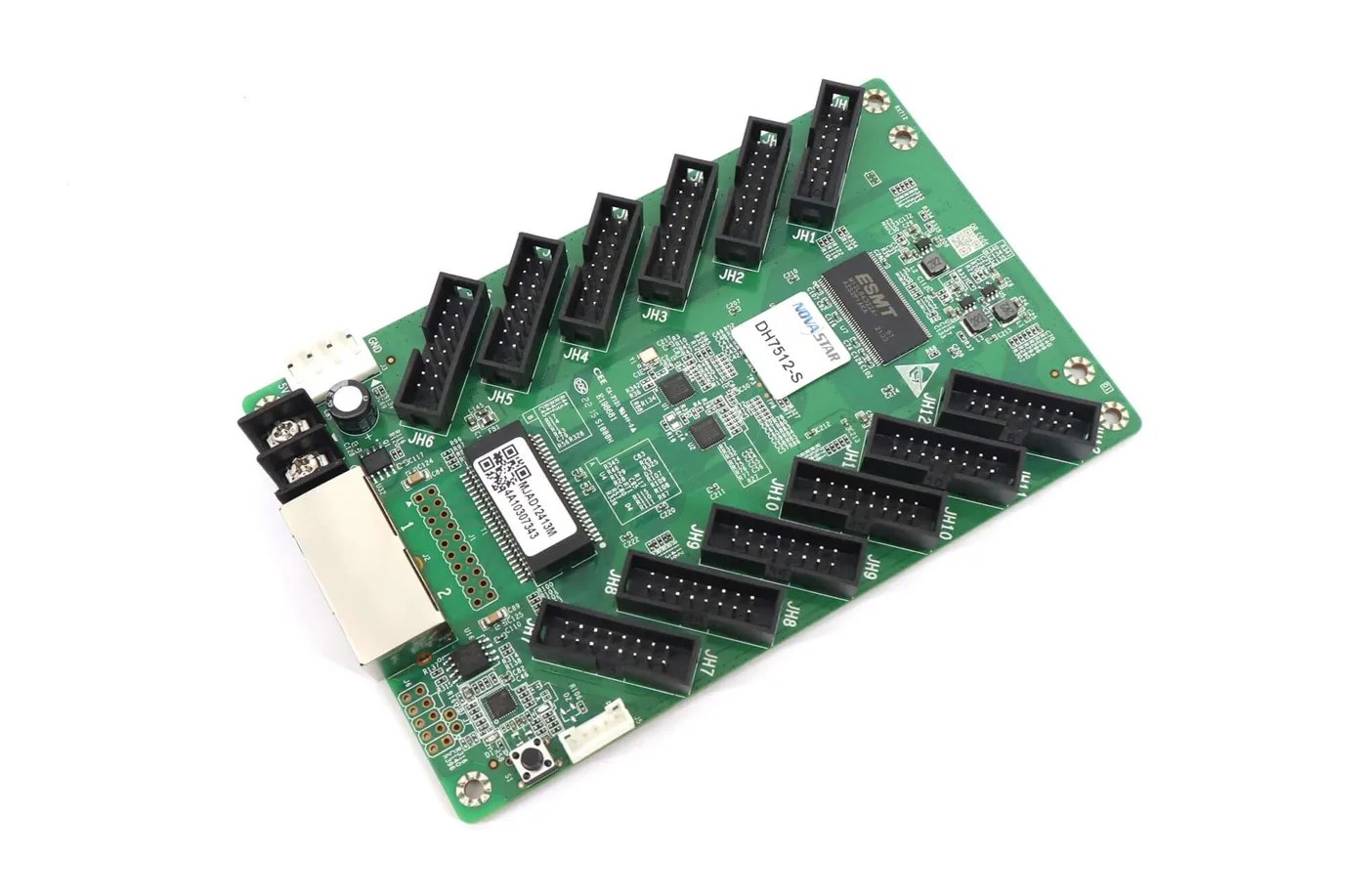
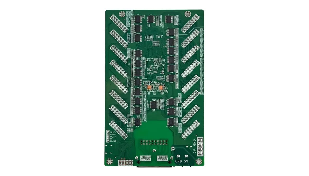
The practical DH7512-S vs DH7516-S difference is the module-output arrangement: twelve HUB75E connectors and up to 24 parallel RGB groups on DH7512-S, versus sixteen connectors and up to 32 groups on DH7516-S. The cited later specifications give both cards the same driver-dependent loading dimensions. More sockets do not automatically mean more total screen pixels or an approved replacement.
This guide is for an AV integrator deciding how to connect modules inside an LED cabinet. It focuses on connector demand, data routing, driver type and configuration so the receiving-card choice follows the cabinet design.
The version references are DH7512-S V1.3.3 and DH7516-S V1.2.3, both dated May 15, 2025, as recorded on the product pages. The DH7512-S page also retains an earlier V1.1.1 download with different parameters. Confirm which document applies to the supplied card.
1. Start DH7512-S vs DH7516-S Selection With Module Routing
Choose the receiving card from the module connections and data arrangement the cabinet actually needs. Count the documented output paths, then check that the module pinout and configuration support the proposed wiring.
01. Count the required connections
The number of modules in a cabinet is not automatically the number of receiver connectors required. A cabinet may have a documented module-cascade arrangement, or it may use separate output branches. Obtain that arrangement from the cabinet design rather than assuming one connector per module.
Draw the receiver position, identify each module and mark every ribbon-cable path. Record the number of output branches and the module sequence on each branch. Include connector orientation and any connection labels used by the cabinet manufacturer.
For DH7512-S vs DH7516-S planning, that drawing identifies whether twelve documented HUB75E connections are sufficient or whether the design requires more. It does not establish that the higher connector count is electrically suitable without reviewing the remaining requirements.
02. Keep physical sockets and data groups separate
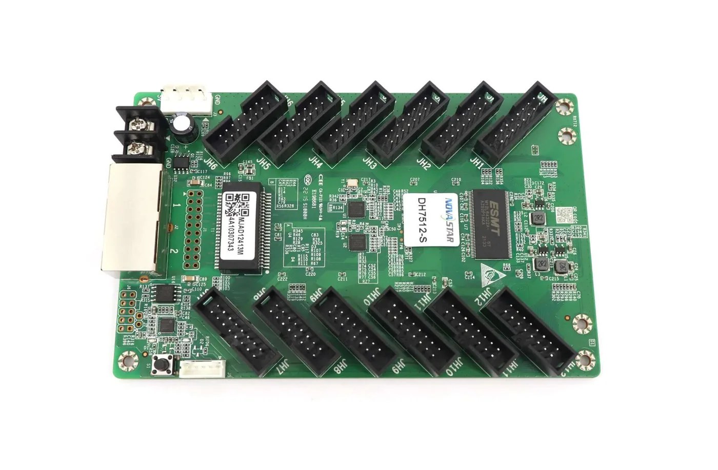
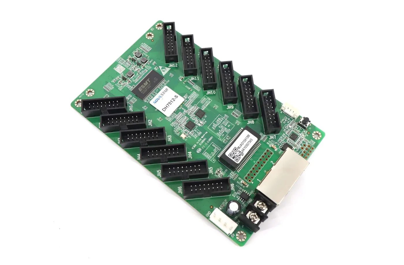
The DH7512-S provides twelve HUB75E connectors and up to 24 parallel RGB data groups. The DH7516-S provides sixteen HUB75E connectors and up to 32 groups. These are related output characteristics, but they should not be replaced with a claim that every socket drives the same number of pixels in every module configuration.
Use the manufacturer’s pin definitions and the module’s data-routing information when allocating outputs. A cable that physically fits can still carry the wrong signals for the intended module. Shared connector terminology is a reason to inspect the pinout, not to skip it.
2. Compare Connector Counts and Conditional Loading
The later DH7512-S vs DH7516-S specifications show equal maximum dimensions under the stated driver conditions. The additional DH7516-S connectors address output arrangement rather than a universally larger pixel budget.
| Parameter | DH7512-S V1.3.3 | DH7516-S V1.2.3 | Design implication |
|---|---|---|---|
| HUB75E connectors | 12 | 16 | Compare the required module-output branches |
| Parallel RGB groups | Up to 24 | Up to 32 | Match the module’s documented data arrangement |
| PWM driver loading | 512 × 512 at 60 Hz | 512 × 512 at 60 Hz | Confirm that the actual driver qualifies for this condition |
| Common driver loading | 512 × 384 at 60 Hz | 512 × 384 at 60 Hz | Do not use the PWM height limit for an unidentified driver |
| DC input | 3.8–5.5 V | 3.8–5.5 V | Verify the supplied revision and power connection |
| Rated current / consumption | 0.5 A / 2.5 W | 0.5 A / 2.5 W | These are receiver figures, not cabinet power demand |
| Dimensions | 145.6 × 91.5 × 19.1 mm | 145.6 × 91.5 × 19.1 mm | Check mounting holes, connector clearance and actual board |
Review the DH7512-S product and revision notes and DH7516-S specifications before using these figures. The shared dimensions are approximately 5.73 × 3.60 × 0.75 in; rounded conversions do not replace a mechanical drawing.
A DH7512-S vs DH7516-S shortlist should therefore contain two different questions: does the card provide the required output arrangement, and can it load the actual cabinet under the required operating conditions? Passing either check alone is insufficient.
3. Calculate Width, Height and Total Pixels
Work from the confirmed module resolution and arrangement, not physical cabinet size alone. Keep width and height visible because a total pixel count can hide an unsupported dimension.
Suppose a hypothetical cabinet contains three modules across and two high, with each module confirmed as 128 × 64 pixels. The cabinet is 384 × 128 pixels and contains 49,152 pixels. That is a numerical starting point for either card, not a validated wiring or configuration example.
Now consider an alternative hypothetical cabinet measuring 256 × 512 pixels. Its total is 131,072 pixels, but its height is 512 pixels. The cited common-driver limit has a height of 384 pixels. A total below 512 × 384 does not make that portrait arrangement acceptable under the stated common-driver dimensions.
That example shows why DH7512-S vs DH7516-S capacity should not be reduced to one multiplied number. Ask for confirmation if a nonstandard arrangement is proposed, and do not assume that rotating content changes the underlying loading conditions.
Record the intended frame rate and any special display functions. The 60 Hz value attached to loading dimensions is not a claim about the panel’s LED refresh rate. Do not advertise a refresh-rate result by copying the receiver’s frame-rate condition.
Also identify how many receivers the cabinet design uses. One receiver per cabinet is a possible design assumption, not a universal rule. If two cards divide a cabinet, each needs an explicit allocation and the screen connection plan must reflect it.
In a DH7512-S vs DH7516-S purchasing request, include both the module drawing and pixel calculation. This allows the reviewer to distinguish a connector shortage from a loading-limit problem and avoids buying a sixteen-connector board to solve an unrelated configuration issue.
4. Verify Driver IC, Scan Mode and Specification Revision
The PWM and common-driver ratings are conditional. Identify the actual driver IC and supported module arrangement before choosing which loading figure applies.
01. Read the module evidence
Photograph the module label, driver IC markings and both ends of the ribbon connection. Record scan mode, pixel dimensions and decoding information available from the module supplier. A pixel-pitch label such as P2.5 does not provide all of these details.
Two modules with the same pitch and outside dimensions may require different driving parameters. Likewise, a replacement module can change the configuration requirement even when the receiving card remains the same. Treat the card, module and saved settings as one reviewed combination.
For DH7512-S vs DH7516-S selection, an unidentified driver should remain an open question. Do not select the more favorable rating because it makes the design fit. Ask the cabinet or module supplier to establish the applicable driver condition.
02. Do not blend old and later specifications
The DH7512-S product page records 512 × 384 at 60 Hz and DC 3.3–5.5 V in its retained V1.1.1 document. Its later V1.3.3 comparison uses the separate PWM/common-driver dimensions and DC 3.8–5.5 V. Mechanical and storage-environment figures also differ.
The same page notes feature-description changes between revisions. Earlier descriptions of color management, 18Bit+ or brightness/chroma calibration should not be presented as universal promises for every supplied DH7512-S. Confirm the required function against the appropriate document and firmware.
This version discipline matters even in a new cabinet build. A purchasing team may receive an older PDF from one source and a later board from another. Keeping the document identity beside the proposed part prevents a DH7512-S vs DH7516-S comparison from silently mixing those sources.
5. Review Calibration, Mapping and Backup by Their Purpose
Maintenance features solve different problems and require their own conditions. Mapping, calibration and backup should each have a defined role in the cabinet specification.
The later product descriptions document brightness calibration through NovaStar’s calibration system, adjustment of dark or bright lines, multi-batch brightness adjustment and rotation in 90-degree increments. They also attach controller conditions to 3D and independent RGB Gamma functions.
Describe the result needed by the installation. Identifying the location of a cabinet is different from correcting its brightness. Reducing visible seams is different from changing the source layout. This keeps the DH7512-S vs DH7516-S review focused on the functions the integrator will actually commission.
Mapping 1.1 displays controller, Ethernet-port and receiver information for identification. Retain the resulting connection record with the project. If technicians cannot identify which board belongs to which cabinet position, a later service call becomes harder even when the receiver itself is functioning.
Loop backup requires primary and backup network connections. Dual program backup concerns stored firmware copies. Neither description should be converted into a claim that every possible cable, power or controller failure is covered.
For an installation requiring redundancy, draw the intended route and specify the failure that the backup is meant to address. Verify that arrangement in the complete system. The number of module connectors in the DH7512-S vs DH7516-S comparison does not establish the network-backup design.
6. Commission One Cabinet Before Applying the Design Widely
A controlled cabinet test should validate the proposed hardware, module parameters and mapping before the settings are used across an installation. Preserve the original working records when changing an existing screen.
| Stage | Evidence | Decision supported |
|---|---|---|
| Hardware identity | Card model, revision information and board photographs | The supplied part matches the reviewed design |
| Module identification | Driver IC, scan mode, resolution and pinout | The loading condition and module parameters are applicable |
| Output routing | HUB75E branch drawing and connector orientation | The connector count and data arrangement are sufficient |
| Image validation | Full coverage, colors, orientation and mapped image | The cabinet is displaying the intended content |
| Persistence | Saved configuration and controlled restart result | The accepted state is retained |
| Service handover | Approved files, spare-part identity and connection map | A future technician can reproduce the setup |
Have a qualified technician isolate power before moving boards or internal cables, and follow the cabinet service instructions. Do not use a powered trial connection to discover an unknown pin assignment. Keep the approved supply arrangement and polarity in the record.
A DH7512-S vs DH7516-S validation should use representative content as well as test colors. Check text and image edges across the complete cabinet so a routing error is not hidden by a uniform pattern. Record any required calibration or supported special-function test separately.
Keep a distinction between a file saved to the service computer and settings saved to hardware through the applicable procedure. After a controlled restart, confirm the normal image and cabinet position again. A correct temporary display is not the same as a completed service handover.
If the job began with a dark or distorted cabinet, first rule out power, cabling, modules and configuration. The receiving-card replacement guide provides that general diagnostic sequence. Do not buy a different receiver simply because its connector count is higher.
Finally, label the approved spare with the cabinet type and configuration identity. A card that worked in one prototype should not become an unlabeled universal spare for several screens. Keeping that boundary clear makes the final DH7512-S vs DH7516-S decision useful for both purchasing and maintenance.
7. Use Output-Branch Examples Without Assuming a Wiring Design
A DH7512-S vs DH7516-S review can use branch counts to explain a requirement, provided the example is clearly separated from an approved wiring plan. Connector arithmetic does not determine the module’s supported cascade arrangement.
Suppose a hypothetical cabinet design requires ten independently documented HUB75E output connections. Both twelve and sixteen physical connectors exceed that count. The next question is not which board has more unused sockets; it is whether the module data arrangement, driver condition and cabinet load are supported.
Now suppose a different hypothetical design requires fourteen such connections without changing its approved module routing. Twelve physical connectors would not meet that stated requirement, while sixteen would pass this one counting check. The larger connector count still does not prove that the second design meets the card’s other limits.
These examples deliberately avoid prescribing how modules should be cascaded. That information must come from the actual module and cabinet design. The examples show where a DH7512-S vs DH7516-S decision can be affected by output branches, rather than suggesting a universal number of modules per socket.
Prepare a drawing that numbers the branches and identifies the modules served by each one. If an arrangement uses several data groups, record the approved allocation rather than assuming a group count based only on how many ribbons are visible in a photograph.
Keep a second drawing for the LED data path outside the cabinet. The internal HUB75E branch arrangement is different from the controller’s Ethernet-port allocation and receiver sequence. Confusing these two drawings can make a cabinet appear to have an output shortage when the actual issue is mapping.
For a repeat cabinet build, label the approved wiring revision. If a supplier later changes the module driver, connector assignment or scan arrangement, review the configuration again. An unchanged outside cabinet size does not establish that the earlier receiver settings remain appropriate.
For a replacement purchase, describe whether the original card’s full model suffix is visible. Keep DH7516 and DH7516-S distinct, and do not assume that an older card without the S suffix shares the later reference’s parameters. The same discipline applies to other closely named receivers.
Ask the supplier to state the proposed card, applicable document and required configuration work. A complete response should address the unknown module or wiring condition, not just repeat the larger model’s connector count. Keep that response alongside the bill of materials.
After the test cabinet is accepted, use the approved arrangement consistently and preserve the results. Record any card revision or firmware differences noticed during production. Unexpected differences should be reviewed before configurations are copied across additional cabinets.
This record also helps a technician decide which spare to carry. The spare should match an identified cabinet design and have the appropriate approved files available. A sixteen-connector card should not be labeled suitable for every twelve-connector cabinet merely because it has additional sockets.
The resulting DH7512-S vs DH7516-S choice is then based on an identifiable requirement: enough supported output connections, suitable loading conditions, correct electrical integration and a configuration that has been validated on the actual module arrangement.
Frequently Asked Questions
Keep the DH7512-S vs DH7516-S comparison with the approved cabinet drawing. The spare-part decision should remain tied to that drawing and its tested configuration, rather than being generalized to every screen using a similar connector.
Can an unused HUB75E socket stay unconnected?
Follow the approved module-routing and configuration plan. Having unused physical connectors does not itself identify a fault, but the cabinet configuration must match the connected outputs. Do not invent a wiring arrangement solely to occupy every socket.
Can I split a ribbon cable to connect extra modules?
Do not assume an unreviewed splitter preserves the required signals or loading. Obtain the module supplier’s supported routing and receiver configuration. A connector-count problem should be solved with an approved design, not an improvised cable branch.
Does the specification download contain firmware?
The linked DH7512-S download is identified as a specification PDF, not a firmware package. Obtain firmware for the exact board through the appropriate supported process; do not treat any file linked beside a product as an update.
Does more connector capacity improve image quality?
Connector count describes output arrangement. Image behavior also depends on the modules, driver IC, configuration, calibration and supported control chain. A DH7512-S vs DH7516-S comparison does not establish an image-quality improvement from four additional sockets.
Can I reuse a working configuration from another cabinet?
Only after confirming that cabinet’s modules, wiring and hardware match the intended target. Preserve the original files and validate a single cabinet. A shared pixel pitch or similar outside appearance is insufficient.
Send a Module-Routing Drawing With the Card Request
For stored-content signage, the AD20 playback guide covers the upstream operating workflow. For a compact receiving-card design, consult the A10s revision and compatibility guide instead of treating different receiver families as interchangeable.
For a DH7512-S vs DH7516-S inquiry, provide the module layout, required HUB75E branches, driver IC, scan mode, cabinet pixels and controller model. Include photographs of an existing assembly if relevant. Ask LED Mall to review the proposed receiving card against those details before ordering.