
LEDMall Blog
How to Test LED Screen Chip Reliability and Stability
Oct
To test LED screen chip reliability and stability, measure representative samples before and after controlled operation, keep drive current and temperature consistent, and compare light output, electrical characteristics and failures against predefined limits. A useful report states what was tested, how it was tested and what the results can support.
This guide covers the light-emitting LED dies and packaged LEDs used in display pixels. Driver ICs, receiving cards and complete LED screens require additional tests. An LED that lights up correctly at the start of a test has passed a functional check; its long-term reliability still needs evidence.
1. Determination of Life Test Conditions
(1) Define Reliability, Stability and the Test Objective
A life test operates a device under specified electrical and environmental conditions for a defined period. Reliability concerns whether the LED continues to meet its requirements over time. Stability concerns changes in its light output, color and electrical behavior under controlled conditions.
Decide whether the task is incoming inspection, production screening, process comparison or product qualification. These objectives need different sample sizes and durations. Bare-die testing evaluates the die in its test fixture; packaged-device testing also includes the effects of encapsulation, bonding and heat transfer. Do not treat their results as interchangeable.
(2) Set Current, Temperature and Acceptance Limits
Start with the LED manufacturer’s datasheet and the intended application. Specify the mounting arrangement, measurement method and operating conditions before collecting results. For an LED screen driven by scanning or PWM, document the pulse conditions as well as the current.
| Test item | What to specify | How to interpret it |
|---|---|---|
| Sample identity | LED model, color, package, wafer or production lot, sample count and selection method. | Results apply to the sampled population under the documented conditions. |
| Electrical stress | Forward current, drive mode and, for pulsed operation, peak current, pulse width and duty cycle. | Use model-specific ratings; average current alone does not describe pulsed stress. |
| Thermal conditions | Ambient temperature, mounting, airflow and the temperature measurement point. | Ambient temperature is not the LED junction temperature. |
| Test duration | Elapsed operating hours, measurement intervals and any interruptions. | A short screening run is not a validated lifetime prediction. |
| Acceptance criteria | Allowed optical change, electrical drift and functional failures, agreed before testing. | Use the applicable product specification or qualification plan; there is no universal pass threshold. |
On narrow screens, scroll the table horizontally to view all columns.
(3) Distinguish Screening from Lifetime Evidence
The earlier version of this article described a low-power LED example using 8–10 samples in 5 mm lamp packages, a 30 mA drive current, an ambient temperature of 25 °C ±5 °C, and observation periods of 96, 1,000 and 5,000 hours. These are historical example conditions, not a universal test specification for modern display LEDs.
In that example, 30 mA was described as 1.5 times the nominal current. Do not apply that overcurrent condition to an unspecified LED. Any accelerated test needs an approved stress plan and an explanation of how the stress relates to the failure mechanism being studied.
A 96-hour run may reveal early problems, but it does not establish a 100,000-hour service life. Longer tests provide more observations, yet converting those observations into a lifetime claim requires a suitable method and supporting data. Report measured operating hours separately from any projected life.
2. Process and Precautions for LED Reliability Testing
(1) Select Representative Samples
Assign every sample a unique identifier and record its lot, package and color. When evaluating wafer uniformity, select samples from multiple wafer regions. When evaluating finished-device production, include the relevant production lots and packaging conditions. A few chips from one wafer cannot, by themselves, prove the reliability of an entire production batch.
Choose sample size according to the test objective, expected variation and acceptable sampling risk. If results vary substantially, investigate the pattern and expand the sample plan where justified. Increasing sample count and increasing electrical stress are different decisions.
Record initial defects and any exclusions with reasons. If the objective is lifetime testing of initially conforming devices, document the screening criteria and the number rejected. If the objective is incoming quality assessment, those initial defects are part of the result.
(2) Measure Photoelectric Parameters Consistently
Measure baseline values before aging, then repeat the measurements at the planned intervals. Use calibrated equipment and, where practical, the same instrument, fixture and operator. Reproduce the measurement current, thermal stabilization procedure, distance and alignment.
Axial luminous intensity is sensitive to viewing angle and positioning, especially for narrow-beam packages. A change in alignment can resemble light-output degradation. Luminous flux measurements can help evaluate total output, but flux and intensity are different quantities and must not be mixed in the same retention calculation.
| Measurement | Record | Comparison rule |
|---|---|---|
| Optical output | Initial and later luminous flux, or luminous intensity at a fixed angle. | Use the same optical quantity and measurement geometry throughout. |
| Forward voltage | Voltage at the specified measurement current and temperature. | Compare each sample with its own baseline; investigate unexpected drift. |
| Color consistency | Color coordinates or dominant wavelength where relevant to the LED type. | Use the same instrument settings and agreed color limits. |
| Functional failures | Open circuits, short circuits, intermittent output and time of detection. | Keep failed samples in the report instead of averaging only the survivors. |
| Test conditions | Current, temperature, interruptions, instrument identity and calibration status. | Separate fixture or measurement changes from actual device degradation. |
Optical output retention (%) = output after testing ÷ initial output × 100. Calculate retention for each sample using comparable measurements. For example, a change from 10.0 to 9.2 in the same optical units gives 92% retention and 8% loss. This is an arithmetic example, not a pass/fail limit.
Report individual results, the spread across samples and failure counts. A good average can hide one severely degraded device. Define the acceptance limits before testing rather than choosing limits after seeing the results.
(3) Account for Resin and Encapsulation Aging
Changes in encapsulant transparency can reduce measured light output even when the LED die is still operating. Distinguish package-related optical changes from changes in the semiconductor itself. Inspect samples for discoloration or other visible changes, and record the exposure history.
Control unintended ultraviolet exposure during a test intended to isolate electrical or thermal aging. If sunlight or UV exposure is part of the intended service environment, evaluate it in a separately defined test. Removing that exposure from every test would not represent outdoor use.
(4) Investigate Packaging and Assembly Effects
Die attachment, wire bonding, encapsulation and mounting can influence reliability. Differences in heat dissipation and mechanical stress may affect the result. Record the package and assembly process so that a process change is not mistaken for a change in die quality.
Microscopic inspection can identify some visible defects, but it cannot rule out every internal failure mechanism. Preserve failed devices for analysis and compare their optical, electrical and physical findings. Packaged-device results are often more relevant to the intended application, while bare-die tests can help isolate specific causes.
3. Design of an LED Life Test Bench
(1) Use Controlled Current for Each Test Channel
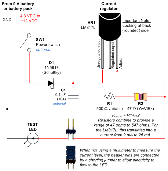
A practical test bench combines a regulated drive circuit, identifiable sample positions, suitable thermal mounting and a measurement log. Series-connected LEDs carry the same current. Directly paralleling LEDs without branch current control can produce unequal currents because forward-voltage characteristics vary.
For parallel test branches, use appropriate current regulation or validated current balancing for each branch. Verify actual branch current rather than assuming that equal supply voltage means equal current. Size the supply for the LED string voltage plus the driver’s required voltage headroom, and check power dissipation.
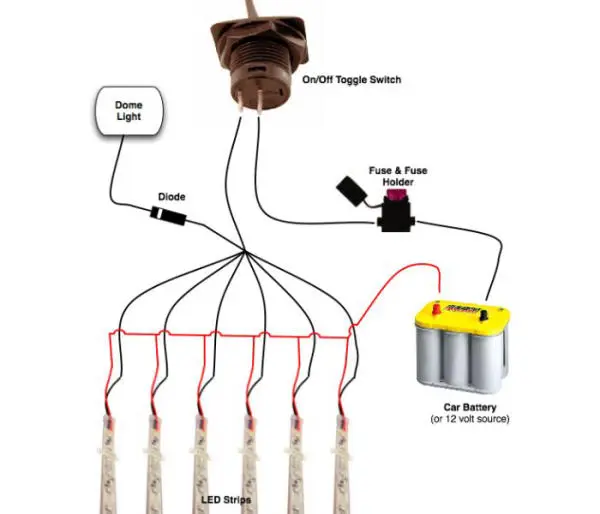
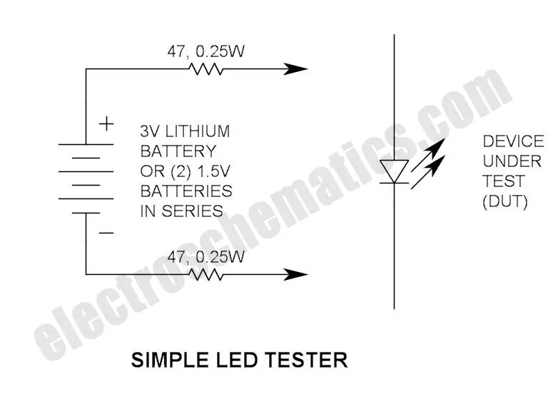
The retained circuit illustrations provide context for test-bench design. Component values and operating limits must be checked against the actual devices before use.
(2) Detect Failures Without Misclassifying Samples
An open LED can interrupt an entire series string. A dark string therefore does not mean that every LED in it has failed. Check individual devices and connections, record the failed position and note when the interruption occurred. A shorted LED also needs to be identified rather than ignored because the other LEDs remain illuminated.
Keep a channel map linking every sample ID to its fixture position. Log power interruptions and measurement pauses, and use actual powered operating time in the report. When changing samples or repairing a fixture, record the intervention so later readings remain traceable.
(3) Match the Bench to the Qualification Plan
Bench capacity alone does not establish test quality. Confirm current regulation, temperature consistency and measurement repeatability across the populated fixture. Prevent one overloaded or faulty channel from distorting the results of neighboring channels.
Operating-life testing addresses only part of reliability. Depending on the product and intended environment, qualification may also include humidity, temperature cycling and other defined stresses. Use conditions appropriate to the specific LED family and application instead of transferring another product’s qualification limits.
Before accepting a supplier’s reliability report, check: the exact model and lot, sample count, test conditions, measured hours, baseline and final readings, acceptance criteria, failures and exclusions. Component-level results do not replace verification of the assembled LED display.
Technical reference context: Cree LED’s XLamp LED Long-Term Lumen Maintenance distinguishes measured light-output maintenance from projected life. Its XLamp LED Reliability Overview illustrates product-specific qualification testing. Texas Instruments’ LED-driver considerations explains current control and series/parallel drive arrangements. These references support the general principles here; their product-specific test conditions are not universal limits for LED screen pixels.
For related display-level checks, read our guide to measuring and verifying LED display brightness.
4. Frequently Asked Questions About LED Screen Chip Testing
(1) How Do You Test an LED Chip for Reliability?
Identify representative samples, measure their initial optical and electrical performance, operate them under documented conditions, and repeat the measurements at planned intervals. Compare each device with its baseline and the agreed acceptance limits, including any functional failures.
(2) Is a 96-Hour LED Aging Test Enough to Prove Long Life?
No. It can provide early screening information under the stated conditions, but it cannot independently validate a long service-life claim. Ask for the measured test duration, sample count, failure data and the basis for any lifetime projection.
(3) What Current and Temperature Should Be Used for LED Testing?
Use the specific LED’s datasheet and the approved test plan. Record drive mode, current, pulse conditions where applicable, ambient conditions and the temperature measurement point. The historical 30 mA example in this article should not be copied to other LEDs without validation.
(4) What Is the Difference Between LED Burn-In and a Life Test?
Burn-in generally refers to a defined screening run intended to expose early defects. A life test evaluates performance and failures over a specified operating period. The name alone is insufficient: compare the actual stress conditions, duration, sample plan and acceptance criteria.
(5) Does Passing an LED Chip Test Guarantee a Reliable LED Screen?
No. The assembled display also depends on its driver electronics, power supplies, solder joints, connectors, cooling and operating environment. Evaluate the finished screen for brightness and color consistency, pixel defects and stable operation under its intended settings and conditions.