
LEDMall Blog
NovaStar HUB75E Connectors: Module Ports and Compatibility
Nov
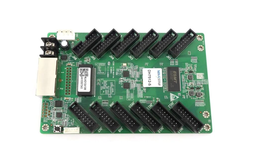
NovaStar HUB75E connectors are module-output connections found on receiving cards such as DH7512-S and DH7516-S. They are different from the card’s Ethernet data connections and from the high-density connections used on compact receivers with a separate hub board. The connector name helps identify the connection family; it does not prove that a particular LED module, cable or configuration is compatible.
This explanation is for a small LED sign builder identifying the connections inside a cabinet before ordering parts. It covers what to check and what cannot be decided from a photograph. It does not provide a universal pinout or authorize a powered wiring experiment.
The examples use the manufacturer’s DH7512-S V1.3.3 and DH7516-S V1.2.3 specification references retained by LED Mall. Verify the drawing and supplied revision for the actual assembly, especially when replacing a board in an existing sign.
Where NovaStar HUB75E Connectors Fit in the Signal Path
The receiving card sits between the LED data path from the sending equipment and the connections that drive the cabinet’s modules. Identify those two sides separately before counting outputs or choosing cables.
For DH7512-S and DH7516-S, the HUB75E connectors provide the module-facing connection arrangement. The card’s Ethernet ports serve a different role. A module ribbon cable and a cable carrying LED data between receiving cards are not interchangeable simply because both move display information.
A typical purchasing mistake is to ask for “more ports” without naming which ports. The request might mean module connections inside one cabinet, LED data outputs on a sending controller, or a control-network connection. These are different requirements and need different specifications.
| Connection | Role to identify | Evidence needed |
|---|---|---|
| HUB75E module output | Route receiver output signals toward compatible modules | Receiver drawing, module pin assignment, cable orientation and approved routing |
| Receiver Ethernet port | Carry the supported LED data path between sending equipment and receivers | Port labels, connection diagram and system topology |
| Compact receiver high-density connection | Mate the receiver to a suitable hub-board assembly | Both mating drawings, mounting arrangement and signal allocation |
| Power connection | Supply the board through its documented electrical connection | Specified voltage, polarity, connector and cabinet power design |
When discussing NovaStar HUB75E connectors with a supplier, send a readable photograph of the full card as well as the connector area. The complete model label and board orientation help distinguish an actual module output from a nearby connection with another purpose.
What the Connector Count Can Tell You
A connector count describes the physical output arrangement. It does not independently establish the card’s supported pixel dimensions, a module count, or the operating conditions for the display.
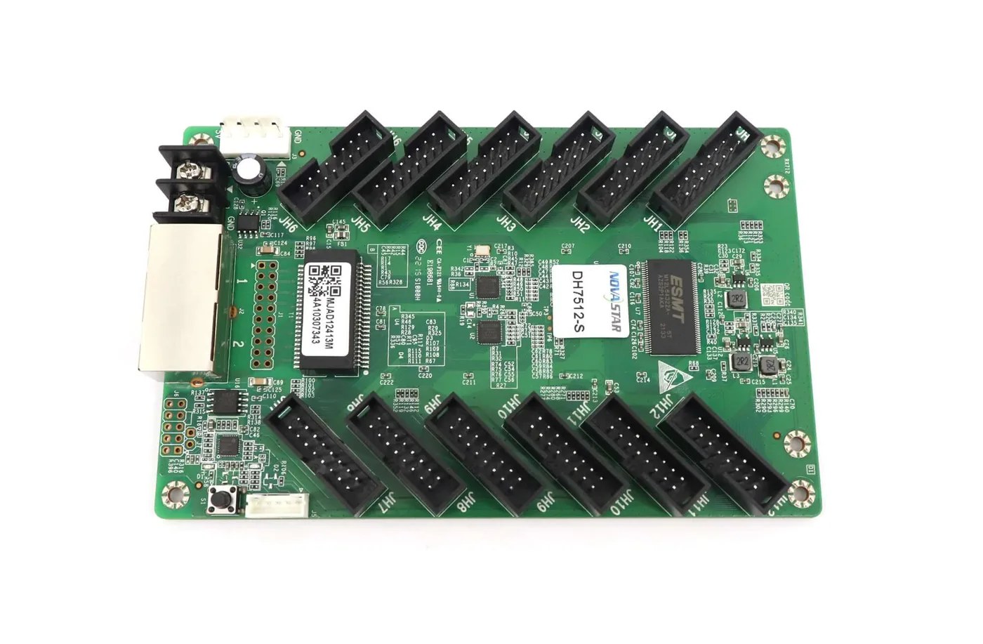
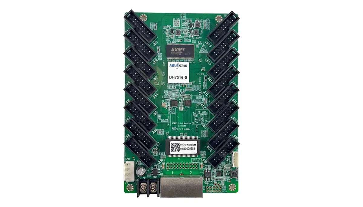
The cited DH7512-S reference lists twelve standard HUB75E connectors and up to twenty-four parallel RGB data groups. The DH7516-S reference lists sixteen connectors and up to thirty-two groups. Those figures describe these two models under their stated specifications; they are not a universal rule for every receiver with a similar connector.
For NovaStar HUB75E connectors, count the module routes required by the approved cabinet design. Do not assume that one connector always means one module. Module pixels, scan arrangement, driver hardware and the documented data routing determine how the cabinet can be arranged.
As an arithmetic example, four verified modules across and two high, each with 128 × 64 pixels, form a 512 × 128 pixel cabinet. That calculation describes eight modules and the resulting area. It does not state how many outputs to connect, how the modules are driven, or whether a proposed receiver supports the arrangement.
The loading conditions must be checked separately. In the cited DH references, the maximum differs between PWM driver ICs and common driver ICs. A count of NovaStar HUB75E connectors cannot replace the correct driver-dependent loading specification. Our DH7512-S and DH7516-S comparison covers those model-specific selection details.
Why a Matching Socket Is Only the Start
A connector that appears to fit does not establish the signal assignment, electrical requirements or supported configuration. Compare the actual documentation for both ends of the connection.
Before connecting NovaStar HUB75E connectors to modules, obtain the approved pin assignment and identify cable orientation from the relevant drawings. Do not infer orientation from the color of a ribbon stripe alone. Cable and board markings need to agree with the documented assembly.
Record the module model and pixel resolution, readable driver IC markings, scan arrangement and intended output routing. Keep these details with the cabinet drawing. The module’s pixel pitch is useful for identifying the display, but pitch alone does not describe the electrical or configuration requirements.
Power deserves its own review. Identify the receiver’s specified power input and the cabinet’s module-power arrangement instead of assuming that a data cable provides all required power. Qualified personnel should isolate power before reconnecting internal cables and follow the cabinet’s service instructions.
If any connector identity is unresolved, request the missing drawing before testing. A powered trial is not a suitable method for discovering an unknown pin assignment. The practical value of identifying NovaStar HUB75E connectors is that it narrows the questions; it does not remove the need to answer them.
A Compact Receiver May Need a Separate Hub Board
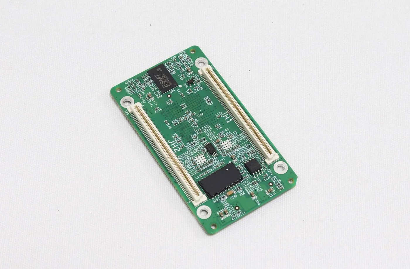
Some receiving cards use high-density connections that mate with an appropriate hub board. Do not treat the bare receiver as though it provides the same direct module-connector layout as the DH examples.
The A10s Plus V1.0.3 reference describes high-density connectors. Its integration therefore requires a review of the mating hub board, mechanical alignment and assigned signals. A small board footprint is not evidence that the receiver can be plugged into an existing module cable without that assembly.
A cabinet photograph may show NovaStar HUB75E connectors on a hub board rather than on the receiving card itself. Identify which component contains the connectors, then obtain both part identities. Replacing only the receiver still requires compatibility with the hub board that remains in the cabinet.
Compare the hub-board model and revision, receiver orientation, mounting positions, clearance and module routing. The A10s Plus product reference can help identify the receiver, while the cabinet supplier must identify the appropriate mating assembly.
Keep the Wiring Record With the Configuration
Hardware identity and configuration need to describe the same accepted cabinet. An unexplained file or a photograph of a similar card is insufficient for a repeat build.
For NovaStar HUB75E connectors in a new sign, label the approved output routes on the cabinet record and preserve the matching configuration. Include the module arrangement and pixels assigned to each receiver. Keep the screen connection map separate so another technician can understand where the cabinet sits in the complete display.
For a replacement, photograph the original orientation and connections before removal. Record the original receiver and hub-board identity, and retain the accepted files. Do not change several unidentified wiring and configuration conditions at once, because a changed image would then be difficult to interpret.
After an approved assembly is configured, check the whole cabinet image, color order, orientation and position within the display. Confirm the accepted state after a controlled restart under the site’s service procedure. A single correct-looking patch does not establish that every module route and cabinet coordinate is correct.
Frequently Asked Questions
Can a standard network switch expand module outputs?
It does not turn an Ethernet connection into additional HUB75E module outputs. Follow the supported LED data topology and choose a receiver assembly with the required module-driving arrangement.
Does a board photograph provide enough information to order a replacement?
It can help identify the model and visible connectors, but it cannot establish every pin assignment, firmware requirement or module configuration. Include the cabinet records and readable labels with the photograph.
Can I treat the E suffix as a universal scan-setting instruction?
No. Do not derive a supported scan arrangement or a pin assignment from a connector name alone. Use the actual receiver and module documentation and the cabinet’s approved configuration.
Does an incorrect color mean the connector is damaged?
No. Configuration, module hardware, routing and other system conditions also need diagnosis. A symptom alone does not identify a failed connector or prove that a different receiver is required.
Identify the Cabinet Connections Before Ordering
For questions about NovaStar HUB75E connectors, provide the card and module labels, connector photographs, hub-board identity, module pixels and approved wiring record. Review the DH7512-S listing and DH7516-S listing, then ask LED Mall to check the proposed connection arrangement before purchasing.