
LEDMall Blog
NovaStar A8s Pro vs A10s Plus: Cabinet Compatibility Guide
Nov
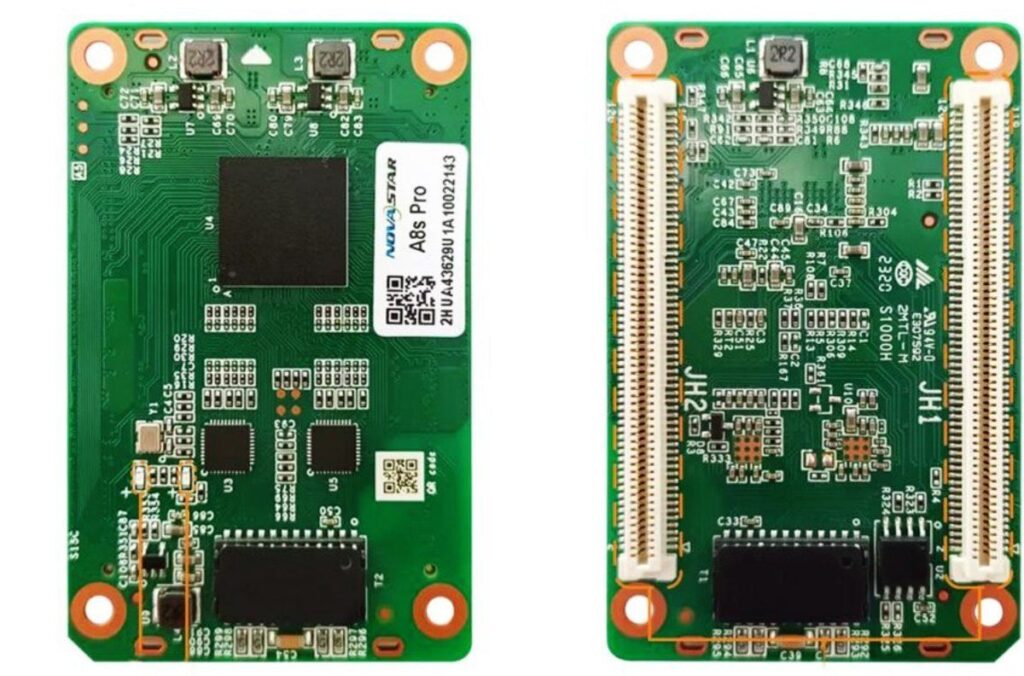
The main A8s Pro vs A10s Plus decision is cabinet compatibility and the functions the complete system can support. The cited A8s Pro specification provides up to 40 parallel RGB data groups, compared with 32 for A10s Plus; both list a maximum 512 × 512 pixel area. Their different mechanical dimensions and revision-dependent features mean that neither should be treated as an automatic replacement for the other.
This guide is for an AV integrator preparing a receiving-card specification for an LED cabinet. It explains which differences affect the hub board, module routing, calibration workflow and spare-part record, so purchasing can request a defined configuration.
The baseline is the A8s Pro V1.1.0 information retained on LED Mall and the manufacturer’s A10s Plus V1.0.3 document. A later A8s Pro V1.3.1 document adds revision-specific information. These references describe different products and document dates; confirm the applicable hardware and firmware before ordering.
1. Start the A8s Pro vs A10s Plus Review With the Cabinet
A receiving card must match the cabinet’s electrical connections, module-driving requirements and configuration. A larger model number, a shared brand or a similar maximum pixel count does not establish that match.
Identify whether this is a new cabinet design or a replacement inside an accepted installation. For a new design, the integrator can review the receiver and hub board together. For a replacement, the existing assembly sets additional constraints: mounting positions, connector alignment, approved module routing and the files needed to restore the display.
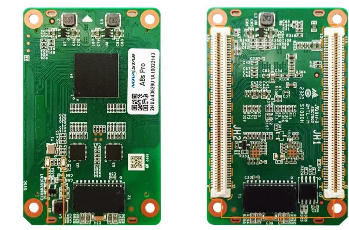
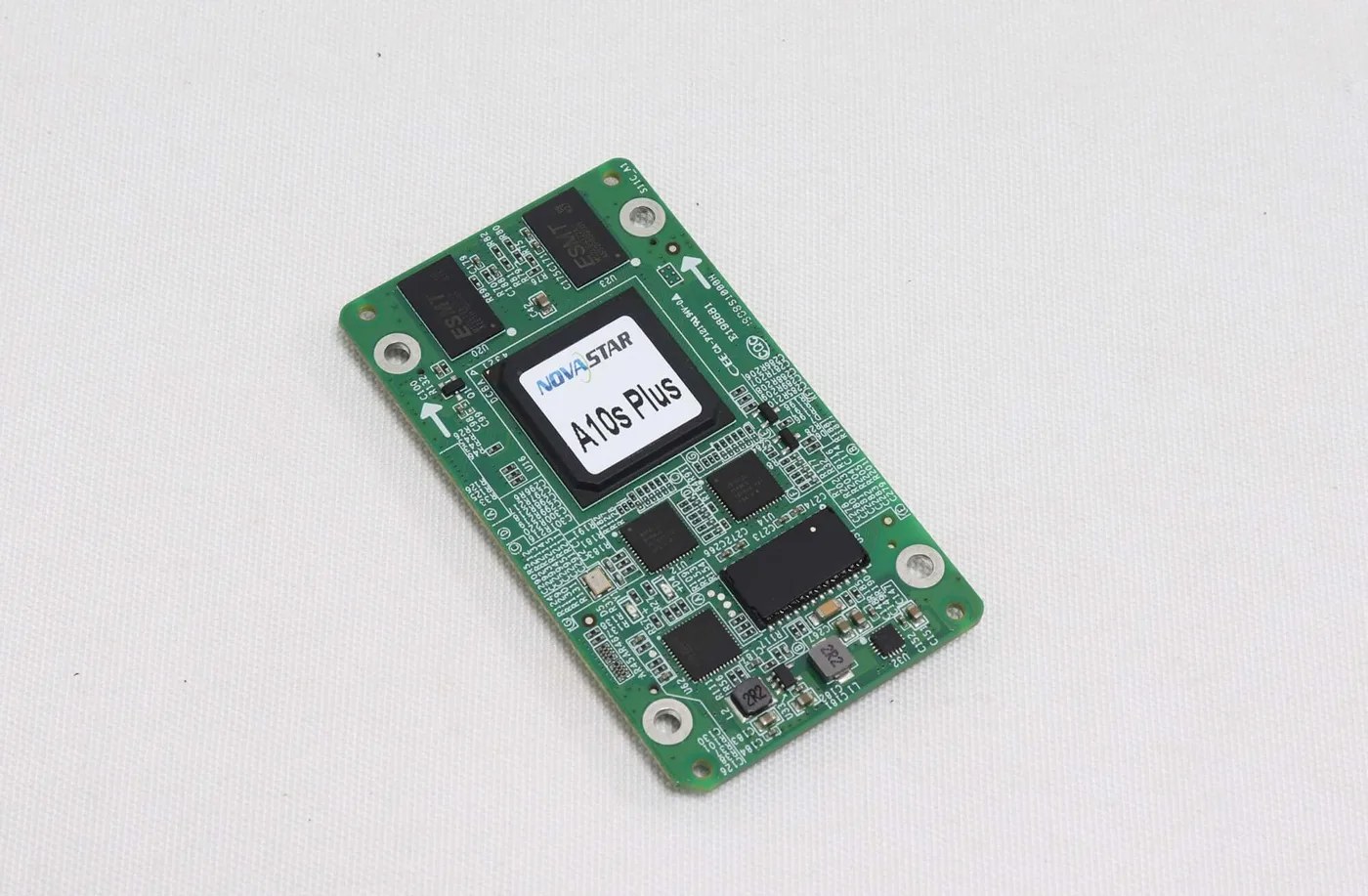
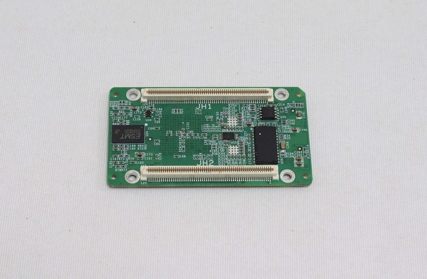
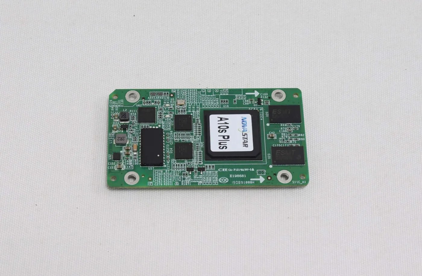
Write down the complete model name from the board label. A8s Pro is not A8s or A8s-N. A10s Plus is not A10s Plus-N or A10s Pro. A quotation that omits a suffix should remain an open item until the proposed part is identified. Photographs help establish the label, but they do not prove firmware or pin compatibility.
Next, obtain the cabinet’s module resolution, driver IC, scan arrangement and hub-board drawing. If the assembly is already working, preserve its receiver settings and connection map before any change. Keep that record separate from a supplier’s generic product brochure.
Use the A8s Pro product and version notes and the A10s Plus specifications as the starting references. The review is complete only when those specifications have been related to the actual cabinet.
2. Compare Parameters Under Their Stated Conditions
The most useful comparison keeps data groups, loading dimensions and physical integration separate. Extra data groups describe an output arrangement; they do not by themselves create additional screen pixels.
| Item | A8s Pro | A10s Plus | Purchasing implication |
|---|---|---|---|
| Reference used here | V1.1.0 product-page reference | V1.0.3, February 26, 2021 | Record the document alongside the supplied revision |
| Maximum loading dimensions | 512 × 512 at 60 Hz | Up to 512 × 512 pixels | Confirm operating conditions; do not infer a different frame-rate rating |
| Parallel RGB data groups | Up to 40 | Up to 32 | Match the cabinet’s approved data routing |
| Serial data groups | 64, expandable to 128 | 64, expandable to 128 | Verify the required mode and pin allocation |
| Interface type | High-density connectors | High-density connectors | A shared interface description is not a pinout approval |
| DC input range | 3.8–5.5 V | 3.3–5.5 V | Check the actual supply and supplied board revision |
| Listed dimensions | 70.0 × 45.0 × 8.3 mm | 80.0 × 45.0 × 7.9 mm | Compare mechanical drawings and clearance |
| Rated receiver consumption | 2.5 W | 2.5 W | This is not the cabinet’s total power requirement |
The A8s Pro vs A10s Plus table is a shortlist, not an installation approval. For example, equal rated consumption does not establish the same connector power arrangement. Similar board width does not establish the same mounting-hole location.
The published A10s Plus page also preserves earlier V1.0.0 values, including a 7.3 mm height. Use the value associated with the approved drawing instead of selecting whichever dimension fits the available space. For A8s Pro, a later V1.3.1 document explicitly records a dimensions-diagram update.
Keep the original metric dimensions in the purchasing record. The nominal footprints are approximately 2.76 × 1.77 in for A8s Pro and 3.15 × 1.77 in for A10s Plus. Rounded inch conversions help with planning but should not be used to fabricate an adapter or place mounting holes.
3. Check the Hub Board Before Calling Either Card Compatible
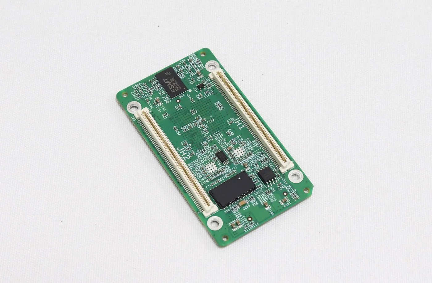
High-density receiving cards connect through a suitable hub board. Review connector positions, assigned signals, mounting and clearance together; an apparently matching connector is insufficient evidence of compatibility.
01. Compare the complete assembly
Ask for a drawing that identifies both sides of the mating connection. Include the hub-board model or revision, receiver orientation, mounting points and the route from the hub board to the modules. A photograph of the bare card cannot show how every signal is used inside the cabinet.
For an A8s Pro vs A10s Plus substitution, the 70 mm and 80 mm board lengths are an immediate reason to investigate fit. Do not assume that changing a mounting pillar solves the rest of the integration. Connector position, component clearance and access for service must also be reviewed.
Qualified service personnel should isolate power before removing boards or reconnecting internal wiring. Follow the cabinet’s service instructions and the applicable mechanical drawing. A trial powered connection should not be used to discover an unidentified pin assignment.
02. Account for every required data group
The additional parallel groups on A8s Pro may matter when the approved cabinet layout requires them. If a documented layout requires more than 32 parallel RGB groups, the A10s Plus baseline does not meet that stated group-count requirement. This observation does not validate the rest of the A8s Pro design.
If the cabinet uses fewer groups, unused capacity does not automatically improve its image. Check the module driver, scan arrangement and supported allocation instead. Avoid converting a group count into a universal number of modules per card.
A useful A8s Pro vs A10s Plus approval therefore names the hub board and module arrangement, not only the receiving card. If that supporting information is unavailable, request it before committing to a replacement quantity.
4. Calculate the Cabinet Load Without Losing Width and Height
Start with module pixels and the number of modules across and high. Compare each loading dimension with the applicable specification, then review driver and operating conditions.
Consider a hypothetical cabinet with four modules across and two high, where each confirmed module is 128 × 64 pixels. The cabinet resolution is 512 × 128, or 65,536 pixels. That arithmetic identifies a proposed load; it does not approve the module wiring, scan settings or operating mode.
Now consider a hypothetical 256 × 768 arrangement. Its total is 196,608 pixels, below 512 × 512 when multiplied, but its height exceeds 512. A smaller total alone does not demonstrate that this arrangement is supported. Seek an explicit loading arrangement for any nonstandard width or height.
In an A8s Pro vs A10s Plus calculation, also state how many receivers divide the cabinet. If the design uses more than one card, document the pixels assigned to each and how those areas connect to the screen map. One receiver per cabinet is a design choice, not a rule that can be inferred from enclosure size.
Keep frame rate separate from LED refresh rate. The 60 Hz attached to the A8s Pro loading reference does not state a universal panel refresh rate. Driver settings, the supported mode and the complete display design must be reviewed for the required result.
Finally, keep the receiver calculation separate from the sending controller’s output allocation. An individual cabinet can fit a receiver while the total wall still exceeds another system limit. The sending-controller comparison explains why the source and output chain need their own review.
5. Specify Image Functions as a Complete Workflow
Calibration, HDR, rotation and low latency depend on more than the card’s name. Specify the required result, then confirm the controller, software, driver IC and calibration arrangements that support it.
The A8s Pro reference describes multi-layer calibration for low-grayscale areas alongside conventional brightness and chroma calibration. The A10s Plus V1.0.3 reference describes Image Booster functions, including color management, precise grayscale and 22bit+. These labels should not be treated as a comparative measurement of two completed screens.
For the A8s Pro vs A10s Plus decision, describe the viewing condition that matters: low-brightness content, color consistency between cabinets or a specified source workflow. Ask how that requirement will be configured and checked on the actual module. A feature listed on a bare receiver is not a record of the finished wall’s performance.
HDR needs compatible upstream equipment. A source carrying HDR content does not establish that every downstream device is configured to handle it. Identify the source format and controller, and request confirmation of the complete path before using HDR as the deciding purchase criterion.
Likewise, rotation in 90° increments is different from arbitrary-angle rotation. The cited product descriptions associate free rotation with MCTRL R5 and SmartLCT. Do not infer that any controller or software combination provides the same operation.
The documented one-frame low-latency statement applies at the receiving-card end and requires modules whose driver ICs have built-in RAM. It is not a measured delay for the complete source-to-screen chain. If timing is important to the project, define which part of the chain must be measured.
Later A8s Pro V1.3.1 documentation describes Thermal Compensation 2.0 and other revised features. The older V1.1.0 product reference does not establish those later functions for every supplied board. Keep the A8s Pro vs A10s Plus feature decision tied to the firmware and document approved for the order.
6. Separate Backup Functions and Preserve Service Evidence
Network backup, a second receiving card and stored configuration backups address different failure paths. Draw the intended arrangement and state which failure it is designed to cover.
Dual-card backup requires a suitable hub-board arrangement with two receivers. Loop backup concerns the primary and backup data paths. Stored configuration and firmware backups are different again. None of these descriptions should become a claim that all controller, cabling, power or module failures are covered.
For an A8s Pro vs A10s Plus project, ask the integrator to identify the normal path and the expected behavior after one defined fault. Keep the answer with the wiring drawing. A spare card in a box is useful for repair, but it is not an automatically operating backup receiver.
Record the accepted configuration files, firmware identity, connection map and any calibration material required by the actual workflow. Do not assume that one exported file contains every item needed to restore a cabinet. Keep copies associated with the correct cabinet type and batch.
For an existing display, use the receiving-card replacement checklist to rule out power, cabling, modules and configuration before buying another board. This guide covers the specific A8s Pro vs A10s Plus design choice; it does not establish that a card is faulty from an image symptom alone.
7. Give Purchasing an Acceptance Record
The final order should identify an approved assembly and the evidence needed to reproduce it. That is more useful than a request for whichever receiver appears to have the longest feature list.
| Check | Record to retain | Question it resolves |
|---|---|---|
| Part identity | Full model, supplied revision and firmware | Is this the exact item reviewed? |
| Mechanical integration | Hub-board drawing, mounting and clearance | Does the complete assembly fit? |
| Module driving | Driver IC, scan arrangement and group allocation | Are the module requirements supported? |
| Loading and mapping | Pixels per receiver and screen connection map | Is each cabinet area assigned correctly? |
| Required functions | Controller, software and validation conditions | Can the requested image workflow be demonstrated? |
| Maintenance | Approved files, restart result and spare label | Can another technician restore the accepted setup? |
Validate one representative cabinet before repeating the configuration across a build. Check its complete image, colors, orientation and normal content, then confirm the accepted state after a controlled restart. Test any required backup arrangement separately rather than assuming a normal image proves redundancy.
For repeat orders, keep the approved revision visible on the purchasing record. If the proposed supply changes, review the affected drawing, firmware or function before accepting it. Previous success with the same abbreviated model name does not establish that every later delivery is identical.
01. Define the scope of a new cabinet purchase
Separate the bare receiver from the rest of the integration in the quotation request. Identify whether the proposed supply includes a hub board, mounting hardware, approved configuration, calibration work or only the card itself. Ask the supplier to list what is included rather than assuming that a photographed assembly is the unit being sold.
For a new design, also name who will approve the prototype and preserve its final files. The purchasing team needs a clear handover point: which cabinet arrangement was tested, which required functions were checked, and which records will accompany repeat builds. This makes quotes with different scopes easier to compare without inventing a price advantage for either model.
02. Keep a replacement job reversible
For a retrofit, retain the original board and its identifying records until the replacement has been accepted. Photograph the original orientation and connections before removal. Keep a working cabinet available as a reference when the service plan permits, and avoid changing several unknown hardware and configuration items in the same trial.
Agree on stopping conditions before testing. An unidentified hub-board revision, an unexpected supply arrangement or an unavailable approved configuration should lead to review, rather than repeated attempts with unrelated files. If an image appears briefly but the accepted state cannot be reproduced after restart, the service handover is incomplete.
These two purchasing situations can lead to different choices even when the required pixel area is identical. New-build integration allows an approved assembly to be developed together; a replacement must also respect the installation’s existing service and recovery requirements.
A completed A8s Pro vs A10s Plus review should leave purchasing with a clear proposed part, an accepted cabinet arrangement and a short list of unresolved conditions. It should not leave the receiving-card choice dependent on an unrecorded conversation.
Frequently Asked Questions
Is A8s Pro a direct upgrade from A10s Plus?
The model names do not establish an upgrade path. Compare the hub board, mechanical drawing, module-driving requirements, firmware and needed functions. A card with a useful additional feature can still require a different approved cabinet assembly.
Does the A8s Pro vs A10s Plus comparison apply to A10s Plus-N?
No. This comparison identifies A10s Plus without the N suffix. Obtain the separate specification for a Plus-N proposal and review its integration requirements rather than borrowing dimensions or electrical values from this article.
Can calibration data be assumed to transfer with a replacement card?
No. Identify which coefficients and files the accepted workflow requires and where they are stored. Ask the cabinet supplier to define the restore procedure for the actual replacement instead of assuming that a new board arrives with the display’s calibration.
Should every cabinet use the receiver with more parallel groups?
No. Choose a supported data arrangement for the actual module design. If the approved cabinet does not need the additional groups, the larger count alone does not demonstrate an improvement in image quality or serviceability.
What should a distributor keep with a spare-card shipment?
Keep the complete part identity, approved cabinet application and relevant configuration reference with the spare. A label that identifies only the brand or pixel pitch is insufficient to distinguish different modules, hub boards and firmware requirements.
Request a Cabinet-Specific Compatibility Review
For an A8s Pro vs A10s Plus inquiry, provide board photographs, the hub-board drawing, module driver and scan details, cabinet pixels, controller model and required functions. Review the A8s Pro listing and A10s Plus listing, then ask LED Mall to check the proposed assembly before ordering.