
LEDMall Blog
NovaStar CVT10 Fiber Requirements: Choosing the Right Cable
Nov
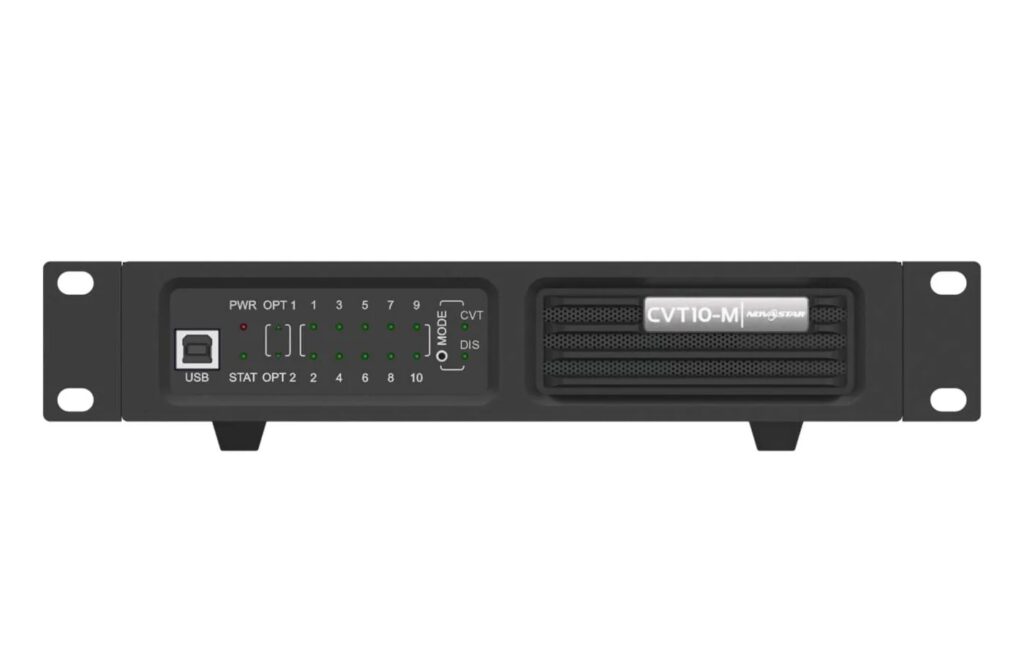
NovaStar CVT10 fiber requirements depend on the model: CVT10-M uses multimode OM3/OM4 twin-core fiber with LC connectors, while CVT10-S uses single-mode OS1/OS2 twin-core fiber with LC connectors. The manufacturer’s V1.2.2 reference lists 300 m (984 ft) for CVT10-M and 10 km (6.2 mi) for CVT10-S. A shared connector shape does not make these two optical arrangements interchangeable.
This guide is for an AV integrator identifying the cable needed between sending equipment and an LED display. It focuses on the optical link and the information required to order it. Receiver loading, screen configuration and Ethernet-port allocation still need their own checks.
The technical reference is the manufacturer’s CVT10 specifications V1.2.2, dated May 31, 2021, retained on LED Mall. Match that reference to the supplied converter, installed optical modules and equipment at the other end before approving a cable.
Match NovaStar CVT10 Fiber to the Model Suffix
Read the complete model label first. The M and S versions describe different optical arrangements; they should not be selected from the distance requirement alone.
| Item | CVT10-M | CVT10-S |
|---|---|---|
| Fiber family | Multimode, OM3 or OM4 | Single-mode, OS1 or OS2 |
| Documented cable arrangement | Twin-core, 50/125 μm | Twin-core, 9/125 μm |
| Connector | LC | LC |
| Module wavelength | 850 nm | 1310 nm |
| Specified transmission distance | 300 m (984 ft) | 10 km (6.2 mi) |
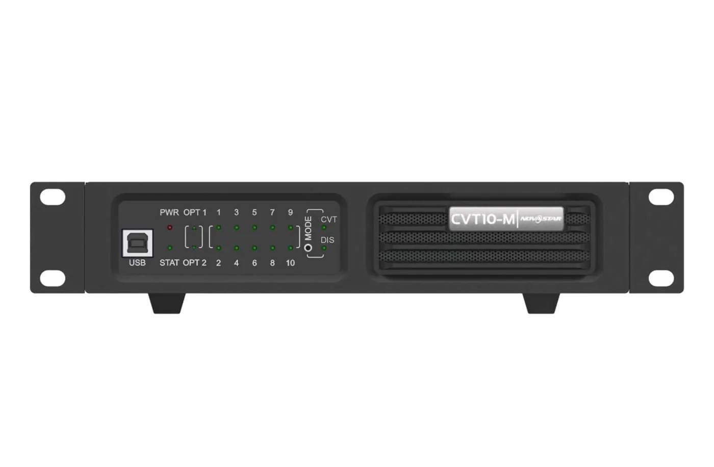
Use the CVT10-M product reference and CVT10-S product reference to identify the proposed equipment. Keep the model suffix visible in the quotation, cable schedule and installation record.
A NovaStar CVT10 fiber order should describe both the converter and the cable. “LC fiber for an LED screen” omits the distinction that matters most here. It also leaves the supplier without an identified receiving endpoint to check.
Identify an Existing Cable Before Reusing It
Reusing a NovaStar CVT10 fiber link requires confirmation of the installed cable’s identity and condition for the intended optical arrangement. A cable already routed through a building is not automatically suitable for a new converter.
Ask for the cable schedule, jacket markings and termination record. Identify the fiber family, number of available cores and connector arrangement at both endpoints. If a patch panel or intermediate joint forms part of the route, include it in the record rather than describing only the visible patch cords.
For a NovaStar CVT10 fiber review, distinguish the route’s measured length from the distance between the two equipment positions. Allow for the actual installed path and service loops in the cable schedule. A floor-plan measurement across a room does not describe the complete cable run.
Keep unconfirmed details marked as open questions. If the cable type cannot be identified, request inspection or appropriate testing by the installation team before choosing a converter around it. Do not use a jacket color or a connector photograph as the sole approval record.
A useful reuse decision therefore names the installed route and its verified properties. It does not simply say “the old fiber worked.” That earlier installation may have used different optical modules, different equipment or a different path through the patching system.
Why an LC Connector Does Not Prove Compatibility
LC identifies the documented connector type. It does not establish that the fiber family, optical modules and complete signal path match.
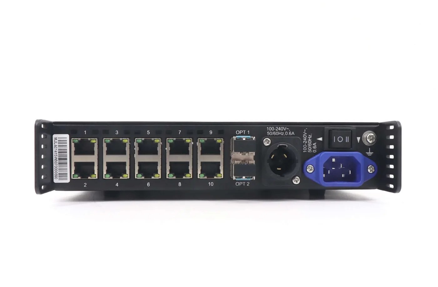
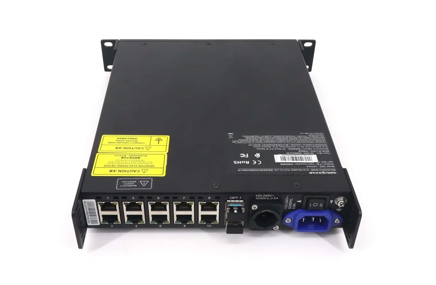
Both versions in the table use LC connections, but their wavelength and fiber requirements differ. For NovaStar CVT10 fiber planning, record the module labels at both ends and compare them with the equipment’s supported arrangement. A connector that can be inserted is insufficient evidence that the link is approved.
The CVT10 reference describes a twin-core arrangement. Do not silently substitute a single-core bidirectional design or assume that an unrelated network transceiver is supported because it has a similar housing. Ask the supplier to identify the complete supported optical assembly.
Document which two endpoints the proposed cable will join. Include the sender’s exact model when it provides the optical connection directly. If another converter is used at that end, identify that converter and its module arrangement as well.
Physical installation and handling should follow the cable and equipment instructions. Have qualified personnel verify terminations and the completed link; avoid experimenting with unidentified modules to see which combination produces an image.
Treat Distance as One Condition in the Link Review
The specified transmission distance is a product reference under its documented optical conditions. It is not a guarantee for every installed route below that length.
For NovaStar CVT10 fiber, verify the cable type, endpoints and route together. Ask the installation team to account for the condition of terminations, any intermediate patching and the accepted link test. A short run with an unidentified or unsuitable arrangement still needs review.
As a planning example, a proposed 350 m (1,148 ft) multimode route exceeds the CVT10-M reference of 300 m. That observation rules out treating the standard distance statement as approval for the proposed run. It does not prove that changing only one end to CVT10-S creates a working link.
The next step would be to review an appropriate single-mode arrangement at both ends and the actual cable installation. Where an existing route is already multimode, selecting a single-mode converter does not change the installed fiber into the required cable.
Keep this engineering decision separate from a purchase quantity. Approving a number of converters before identifying the route can leave the installer with the right count of the wrong optical arrangement.
Define the Two Endpoints and the LED Data Route
A fiber cable is one part of the complete sender-to-display path. Draw that path before deciding which devices belong on the order.
The manufacturer’s application diagrams distinguish a sending card with optical ports from a sending card without them. In the first case, the supported optical connection can run from the sender toward the converter. In the second, the electrical-to-optical stage also needs to be identified. The exact supported arrangement depends on the selected equipment.
A NovaStar CVT10 fiber diagram should label the source-side equipment, the optical run, the converter near the display and the receiver connections. Do not draw an unidentified optical connection as though every sending controller provides the same port or mapping.
Also keep an optical port distinct from an independent extra output group. The V1.2.2 CVT mode identifies OPT1 as the primary optical port and OPT2 as its backup. The presence of two sockets should not be converted into an assumed doubling of the screen capacity.
If the fiber link is established but particular Ethernet outputs remain unavailable, use the separate CVT10 ports 9 and 10 explanation. Changing fiber type is not a substitute for checking sender type, conversion direction and firmware-dependent port availability.
Frequently Asked Questions
Does choosing the longer-distance version increase LED pixel capacity?
No. The optical-distance reference does not independently increase the sender, receiver or supported Ethernet-port loading. Calculate and approve the display’s pixel allocation separately.
Can I assume a fiber cable is included with the converter?
No. Confirm the supplied package and order the required installed-length cable separately when it is not included. A product photograph is not a packing-list commitment.
Does the USB connection carry the display’s fiber link?
No. The cited CVT10 reference assigns USB Type-B to program upgrades from a suitable computer workflow. It is not an optical data connection or a converter-cascading port.
Does a dark screen prove the NovaStar CVT10 fiber cable is faulty?
No. Sender configuration, output allocation, receiver mapping, power and other components can also affect the image. Establish the symptom and inspect the documented signal path before ordering a replacement cable.
Order the Cable With an Identified Optical Arrangement
For a NovaStar CVT10 fiber inquiry, provide both endpoint models, converter suffix, optical-module labels, cable markings, route length and patching details. Compare them with the CVT10 V1.2.2 technical reference, then ask LED Mall to review the proposed equipment and cable requirements before ordering.