
LEDMall Blog
NovaStar MCTRL600 vs MCTRL660 PRO: Signal-Chain Selection
Nov
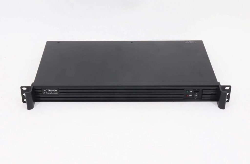
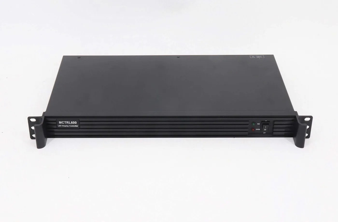
An MCTRL600 vs MCTRL660 PRO choice should follow the source and signal-routing requirements. MCTRL600 provides HDMI/DVI input and four Gigabit LED outputs; MCTRL660 PRO adds 3G-SDI, six Gigabit ports, optical connections, input monitoring and documented synchronization features. Check the exact source timing, bit depth and firmware conditions before treating either controller as suitable.
This guide is for an AV integrator selecting a sending controller for a fixed LED installation. It compares the two specific models, rather than assuming that MCTRL660, MCTRL660 PRO and MCTRL600 are interchangeable names.
The references are the MCTRL600 V2.2.1 specification and MCTRL660 PRO V1.0.0 specification retained on LED Mall. The older Pro reference is dated September 26, 2018. Confirm that the documented capabilities match the actual unit and programs being supplied.
1. Define the Signal Chain Before Comparing Models
A controller selection starts with the source image and ends with the receiving-card system. Identify what equipment already prepares the image and what the sending controller must do within that route.
Record the source connector, output resolution, frame rate, bit depth and color format. Then record the LED wall’s physical pixel resolution, receiving-card types, output chains and any fiber link. Keep source resolution and screen resolution as separate fields.
A request for an HDMI controller leaves several important questions unanswered. Does the source already supply the intended canvas? Is the project expecting additional scaling or a picture-in-picture layout? Does the signal need to reach a remote equipment location? Those requirements may change the product class or the supporting equipment needed.
Do not infer general image scaling from a controller’s ability to accept custom timings. If the job needs a particular processing function, ask for that function explicitly. The MCTRL600 vs MCTRL660 PRO comparison should not conceal a separate need for a video processor.
For a standard HDMI/DVI route over local LED data connections, MCTRL600 may enter the shortlist. For a route needing the Pro’s documented SDI, optical, monitoring or synchronization functions, review MCTRL660 PRO against those requirements. The appropriate choice still depends on the complete configuration.
2. MCTRL600 vs MCTRL660 PRO: Compare Connection Functions
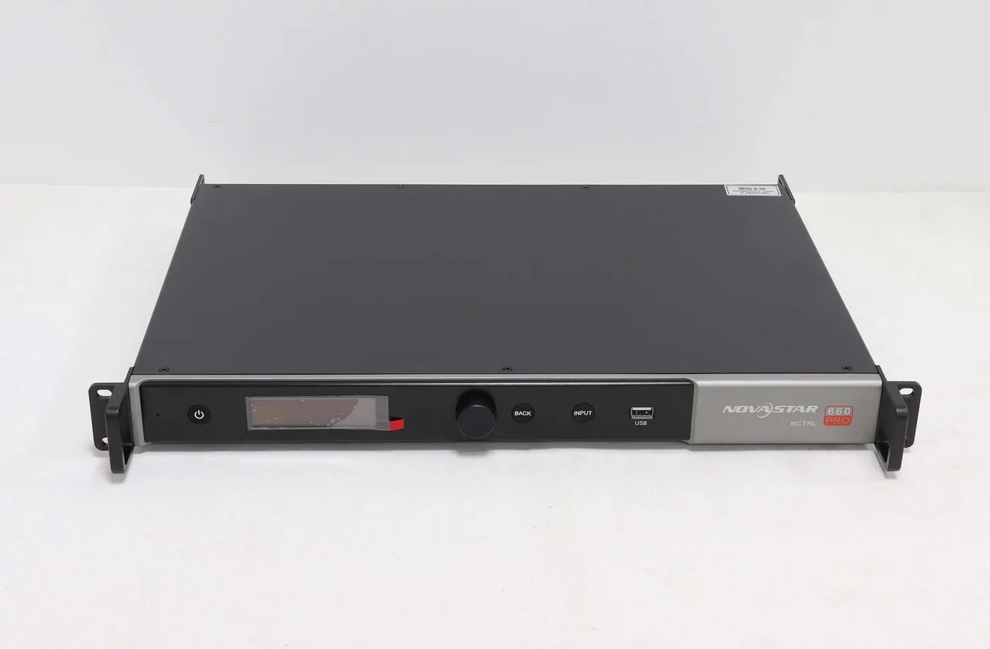
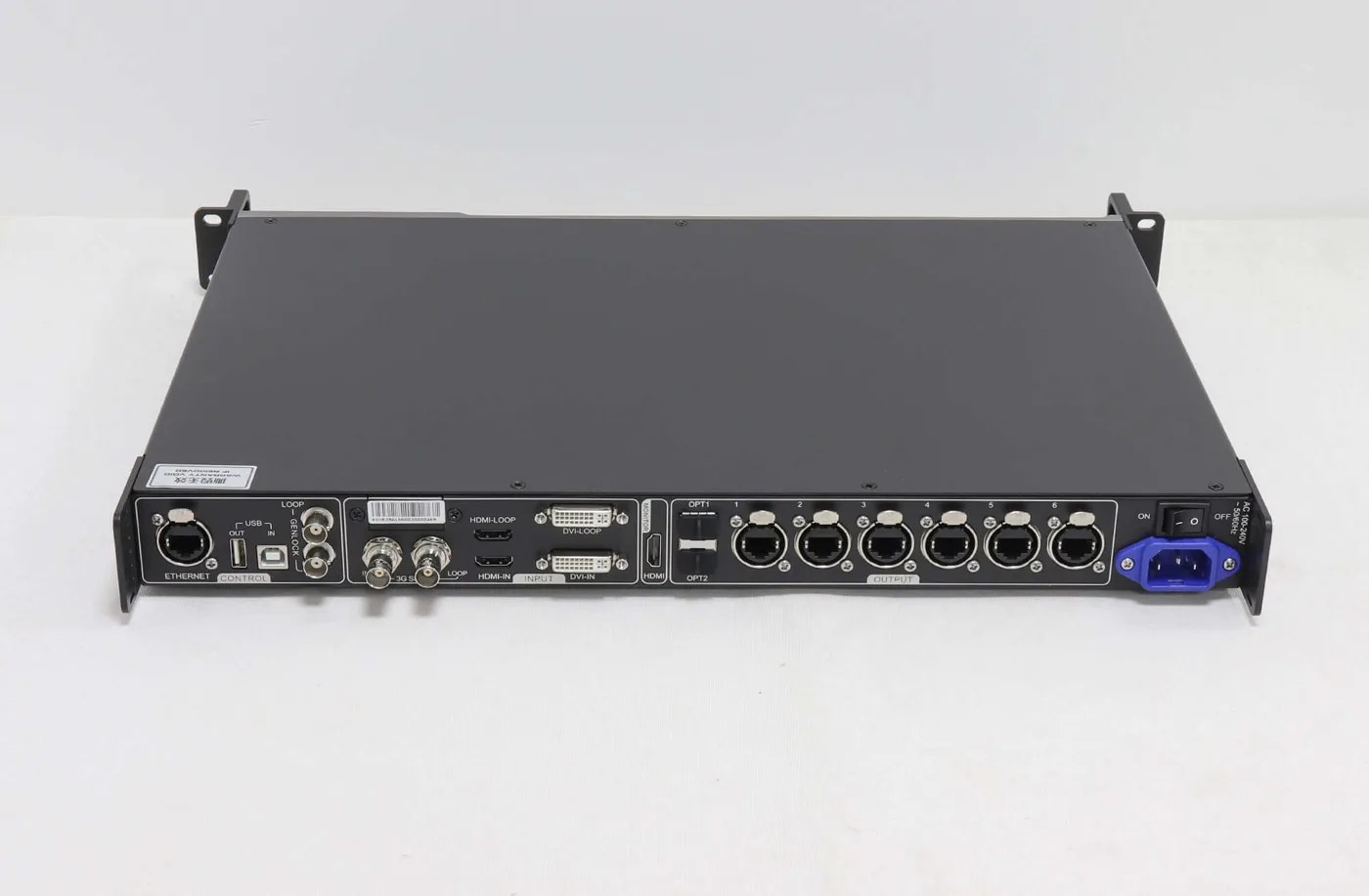
The MCTRL600 vs MCTRL660 PRO difference is broader than two extra Ethernet outputs. The Pro exposes several additional signal paths, each with a distinct purpose.
| Function | MCTRL600 | MCTRL660 PRO | Planning question |
|---|---|---|---|
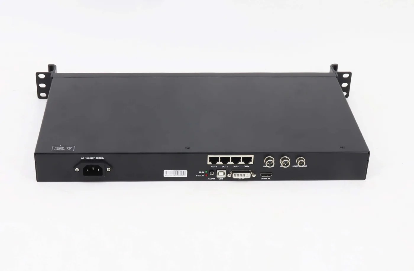
| Video inputs | HDMI 1.3 and single-link DVI | HDMI 1.4a, single-link DVI and 3G-SDI | Which source and exact format must be accepted? |
| LED Ethernet outputs | Four Gigabit ports | Six Gigabit ports | How are cabinet pixels divided across outputs? |
| Optical connections | No optical output listed in the retained specification | Two 10G optical ports; primary and backup roles | What supported converter, fiber and topology are required? |
| Monitoring | Confirm any required external monitoring arrangement | Documented HDMI monitor output at 1920 × 1080, 60 Hz | Does the operator need an input-monitoring display? |
| Cascade/control route | Type-B USB control and UART IN/OUT | Network control, USB IN/OUT and documented Genlock connections | Which devices must be controlled or synchronized? |
| Additional interface | Light-sensor connector | GENLOCK IN/LOOP; Blackburst synchronization | Is ambient brightness control or synchronization actually required? |
The MCTRL600 product page and MCTRL660 PRO product page provide the retained documents and connection descriptions. Check the full model name when requesting the Pro; this comparison does not establish the specifications of the separate MCTRL660.
Count ports only after identifying their purpose. A control connection is not an additional LED output, a loop connection is not automatically another independently processed canvas, and a backup connection is not automatically extra display capacity.
For MCTRL600 vs MCTRL660 PRO procurement, create a cable schedule naming both ends of every connection. This makes it easier to see whether the proposed controller really provides the route required by the installation.
3. Check Resolution and Bit Depth Together
The largest published input timing should not be quoted without its bit-depth condition. Both retained specifications distinguish operating formats that affect the accepted resolution.
01. Resolve the MCTRL600 HDMI discrepancy
The MCTRL600 V2.2.1 video-format table lists 1920 × 1200 at 60 Hz for 8-bit HDMI/DVI, while the HDMI connector section separately states 1920 × 1080 at 60 Hz. The LED Mall product page flags that disagreement. Confirm the intended HDMI timing on the actual unit and firmware before specifying a 1920 × 1200 HDMI installation.
For 10-bit and 12-bit input, the cited table lists 1440 × 900 at 60 Hz in RGB 4:4:4. Documented custom examples include 3840 × 600 at 60 Hz and 800 × 2560 at 60 Hz. Those examples are not permission to invent an arbitrary custom timing for a different setup.
This is a material point in MCTRL600 vs MCTRL660 PRO selection: a design that fits at 8-bit may need a different review at higher bit depth. Keep a source-format requirement in the order request rather than writing only the preferred controller model.
02. Preserve the MCTRL660 PRO program conditions
The MCTRL660 PRO V1.0.0 reference lists up to 1920 × 1200 at 60 Hz on HDMI/DVI at 8-bit using the standard program. For 10-bit or 12-bit operation, it lists 1920 × 960 at 60 Hz with the standard program.
The same document describes 1920 × 1080 at 60 Hz at those higher bit depths only with customized sending-card and receiving-card programs and A8s receiving cards. Do not shorten that requirement to a general claim of high-bit-depth 1080p support for any installed receiver.
The documented Pro custom timings include 3840 × 600 at 60 Hz horizontally and 600 × 3840 at 60 Hz vertically. Its SDI input supports specified video formats, and the input resolution cannot be set through the controller in the same way as a custom computer timing.
A sound MCTRL600 vs MCTRL660 PRO review identifies the exact program combination needed and checks it before purchase. An upgrade promised for later is not evidence that the supplied equipment already satisfies the source requirement.
4. Separate Per-Port Capacity From Accepted Input
Output-port capacity and source-input limits are different constraints. Multiplying the number of ports by a per-port figure does not establish an accepted video timing or a validated wall configuration.
The retained references list a maximum of 650,000 pixels per Gigabit LED port for both models. Four such ports produce an arithmetic sum of 2.6 million pixels; six produce 3.9 million. Those sums describe port budgets, not proof that an arbitrary source canvas of that size is accepted at the required frame rate and bit depth.
Consider a hypothetical 1920 × 1080 wall, totaling 2,073,600 pixels. That total alone does not determine how cabinets should be distributed across four or six ports. Each branch needs a supported pixel allocation, and the controller must accept the intended source format.
Now consider a long narrow hypothetical canvas of 3000 × 700 pixels. It totals 2.1 million pixels, but a total below an arithmetic port sum does not approve that custom width and height. Obtain confirmation of the timing, mapping and receiver conditions instead of relying on multiplication.
The MCTRL600 vs MCTRL660 PRO decision therefore needs two drawings: the source canvas and the LED output map. A receiving-card chain can fit a port’s numerical budget while still having an incorrect cabinet sequence or unsupported module configuration.
Keep a record of the actual receiver models and module parameters. The receiving-card replacement guide explains the hardware evidence to preserve if the controller purchase accompanies cabinet maintenance.
5. Review Optical Paths, Backup and Synchronization Separately
The Pro’s optical connections can support a fiber-based route, but their documented primary/backup roles should remain explicit. Two optical sockets do not mean two independent groups of six LED outputs.
In the documented sending-card mode, Ethernet and optical outputs can carry the same image; OPT1 is primary and OPT2 is backup. One optical port carries the capacity of the six Ethernet ports. In fiber-converter mode, the device converts between optical connections and the six Ethernet ports in either direction.
Specify the intended mode, compatible equipment at the other end and the fiber arrangement. Check optical-module and fiber requirements against the relevant equipment documents rather than assuming every NovaStar optical product mates with every other product.
If a separate converter is proposed, its usable Ethernet ports can depend on the sending device and conversion direction. The CVT10-M product notes illustrate why those conditions need review. That link is a reference to converter requirements, not a statement that every MCTRL configuration is an approved pairing.
In MCTRL600 vs MCTRL660 PRO discussions, ask which failure each backup addresses. Ethernet-port redundancy, optical backup and source continuity are different requirements. Define the normal path and alternate path before scheduling an acceptance test.
The Pro also documents GENLOCK IN and LOOP with Blackburst synchronization. This should not be confused with computer-control cascading. For a multi-controller image, define the required timing relationship and validate it using the supported connection and operating arrangement.
The MCTRL600 reference lists up to twenty controllers through UART, whereas the Pro reference lists up to eight units through its documented USB/Genlock connections. These figures do not make the two cascade methods equivalent or establish a universal multi-screen design.
6. Build an Acceptance Plan Around the Required Features
A completed MCTRL600 vs MCTRL660 PRO selection should leave the integrator with a repeatable setup and evidence that the required functions work. Test the requested configuration rather than every advertised feature.
| Area | Test record | What it establishes |
|---|---|---|
| Input | Accepted timing, bit depth, color format and source identity | The actual source can be used as specified |
| Output map | Port allocation, receiver order and full-wall image | The correct image reaches each cabinet |
| Monitoring, if needed | Monitor connection and observed source image | The operator’s monitoring requirement is met |
| Fiber, if used | Equipment at each end, module/fiber identity and route | The intended optical chain is operating |
| Backup, if used | Failure simulated and alternate path observed | The specific backup requirement is tested |
| Restart and handover | Approved settings, stored files and startup result | The accepted configuration is reproducible |
Use representative video and readable edge markers to check mapping. A uniform test color can hide an incorrect cabinet order or source crop. If audio is required, test its complete route separately from the video result.
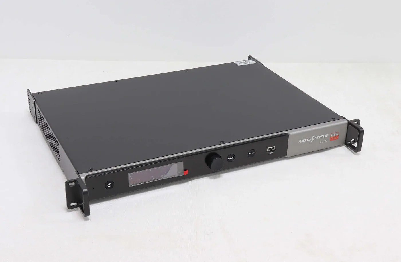
Check rack and cable clearance against the actual unit. The listed MCTRL600 dimensions are 482.0 × 268.5 × 44.4 mm, approximately 18.98 × 10.57 × 1.75 in. MCTRL660 PRO is listed at 482.6 × 349.0 × 50.7 mm, approximately 19.0 × 13.74 × 2.0 in. These are different chassis arrangements even when both are described as 1U products.
The references list 100–240 V AC input, with rated consumption of 16 W for MCTRL600 and 20 W for the Pro. These values do not describe the LED wall’s power demand. Have the power and mounting arrangement checked for the complete installation.
Keep the final source settings, controller identity, firmware/program information and receiver files together. If the MCTRL600 vs MCTRL660 PRO decision changes later because a source or cabinet is replaced, the original evidence makes the new review more precise.
7. State the Required Operating Mode in the Order Record
The MCTRL600 vs MCTRL660 PRO purchase record should identify the supported operating mode that the installation requires. This protects the project from a substitution that preserves the connector count but changes an essential source or transport condition.
For an HDMI computer source, record the chosen output timing, frame rate, bit depth and color format. Include the source equipment or approved export setting where relevant. If the project depends on a disputed or conditional timing, retain the supplier’s confirmation and the actual test result.
For an SDI source, identify the camera or playback equipment and the intended format. Do not assume that the Pro’s SDI connector converts every SDI standard into a supported image. The source-format requirement should remain visible in the acceptance record.
For fiber transport, record the controller mode and the equipment at the other end of the link. Identify the optical modules and fiber type through the applicable equipment documents. A cable described only as fiber does not establish the optical arrangement needed by the system.
For a backup route, describe the specific failure case. A broken data cable, loss of an input source and loss of a controller are separate events. The approved route and required equipment may differ for each, so a quotation line saying redundancy included is not sufficiently precise.
For synchronization, identify the displays or controllers that need to remain aligned and the supported reference arrangement. Keep that requirement separate from centralized control. A computer being able to communicate with several units does not itself establish synchronized video output.
Also identify any processing equipment upstream. If an external processor creates the final canvas, record the timing it sends to the controller. If the design assumes that the sending controller will create a particular layout, confirm that processing function explicitly before purchasing.
Consider a hypothetical installation that changes from a local HDMI source to a remote SDI source. The screen pixel count may remain unchanged, but the source connector, accepted format and transport requirements have changed. Reusing the old controller choice without a fresh review would overlook the actual reason for the change.
In another hypothetical installation, the controller stays local but the receiving cabinets move farther away through a proposed optical route. The source timing may remain identical, while optical compatibility and backup mapping become the new questions. A larger Ethernet-port count is not the answer to those questions by itself.
These examples are planning situations, not claimed customer outcomes. They show why the MCTRL600 vs MCTRL660 PRO decision needs a signal-chain drawing and an operating requirement. Each change should trigger the checks relevant to that part of the chain.
Keep the final approved files and version information accessible to the service team. Name the normal startup state and the connection labels staff should expect. That handover record can reduce guesswork during future maintenance without promising a particular recovery time.
Before accepting delivery, check that the supplied model identity and documented programs match the reviewed proposal. If they differ, resolve that difference before installation. A correct purchasing record is useful precisely because it makes such a difference visible.
Frequently Asked Questions
Is MCTRL660 PRO simply another name for MCTRL660?
No. Keep the full model name in specifications, quotations and support requests. This guide compares MCTRL600 with MCTRL660 PRO and does not establish the capabilities of the separate MCTRL660 model.
Can I use all optical and Ethernet sockets as independent canvases?
Do not assume that arrangement. The retained Pro document describes duplicated image capacity and primary/backup optical roles in sending-card mode. Design independent canvases only through a reviewed, supported system arrangement.
Does a low-latency controller guarantee the full installation’s latency?
No. The source, processing, transport, receiving cards and modules all form the video chain. Define the required end-to-end behavior and measure the actual configuration; a device-level description is not a complete installation result.
Should I select the Pro for every new project?
An MCTRL600 vs MCTRL660 PRO review should identify which Pro-specific function the project needs. Additional interfaces do not solve an unsupported source format, missing processor function or incompatible receiver configuration.
Can the controller’s USB connection play media files?
The retained descriptions identify USB control and cascade functions, not general flash-drive playback. If stored media playback is required, specify an appropriate source or player and confirm the complete connection route.
Send the Source Format and Output Map With Your Inquiry
If your project needs integrated source switching and layouts, review the CMS controller comparison. For a separate optical converter, the CVT10 port-availability guide explains why a ten-port enclosure does not establish ten usable channels in every arrangement.
For an MCTRL600 vs MCTRL660 PRO request, provide screen pixels, cabinet layout, receiving-card models and the source’s exact timing and bit depth. Add fiber, monitoring, synchronization and backup requirements. Ask LED Mall to review the proposed controller arrangement before ordering.