
LEDMall Blog
NovaStar CMS130 vs CMS260: Inputs, Pixel Load and Playback
Nov
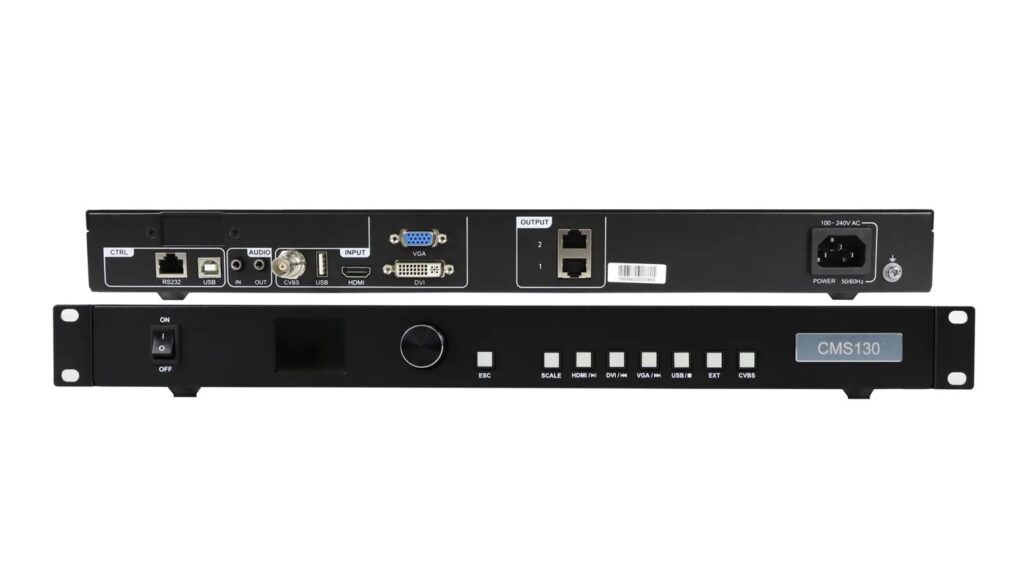
In a CMS130 vs CMS260 decision, choose the CMS130 when a screen within its published 1.3-million-pixel limit needs DVI, VGA, CVBS or documented USB media playback. Consider the CMS260 when the project needs up to 2.6 million pixels, four LED outputs, 3G-SDI or two image layers. Confirm the source format and output map before ordering either controller.
This guide is for AV integrators preparing a controller purchase for a fixed LED installation. It separates input connectors, source timing, screen loading and operating functions so a larger model number does not become the only selection rule.
The comparison uses the original specifications retained on LED Mall’s product pages. A published maximum is a conditional planning limit, not a promise that every combination of sources, receivers and screen settings will work.
1. Start the CMS130 vs CMS260 Comparison With the Actual Job
Write down the wall’s physical pixel resolution, every required source and the operator’s normal workflow before comparing features. These three records usually reveal which controller deserves further review.
01. Measure the display in pixels
Cabinet dimensions in meters or feet do not establish the controller load. Obtain the pixel width and height of each cabinet, the cabinet arrangement and the receiving-card layout. Multiply the resulting screen width by its height, then keep the individual dimensions beside that total.
For example, a hypothetical wall of 1536 × 768 pixels contains 1,179,648 pixels. That falls below the CMS130’s stated total capacity, but it still needs an approved output allocation and compatible receiving cards. The calculation is a preliminary filter, not a validated project configuration.
A second hypothetical wall of 2304 × 1152 pixels contains 2,654,208 pixels. That exceeds the CMS260’s 2.6-million-pixel total even though both dimensions are below 3840. A CMS130 vs CMS260 shortlist cannot solve that requirement by choosing the larger of the two; the project needs another reviewed control arrangement.
02. Inventory the real sources
List each source’s connector, resolution, frame rate, scan type and color format. A laptop with HDMI, an older VGA source and a camera feed over SDI are different requirements. Include any adapters already proposed, because an adapter must deliver a timing and format accepted by the controller.
Record whether staff need stored content without a separate player, a live camera inset, or one full-screen source. The CMS130 vs CMS260 decision changes when the operating requirement changes, even if the LED wall remains identical.
2. Compare the Specifications That Affect Purchasing
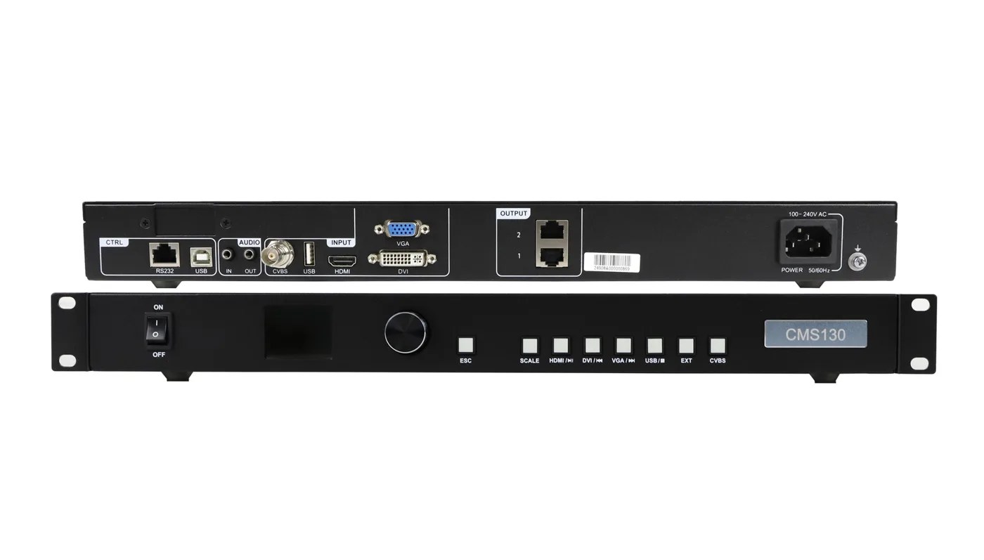
The CMS260 offers a larger total LED load and more outputs, while the CMS130 provides several input types absent from the CMS260. Treat capacity and connectivity as independent checks.
| Requirement | CMS130 | CMS260 | What to confirm |
|---|---|---|---|
| Total LED load | Up to 1.3 million pixels | Up to 2.6 million pixels | Actual screen pixels and port allocation |
| LED outputs | Two Ethernet outputs | Four Gigabit Ethernet outputs | Receiver chain and backup plan |
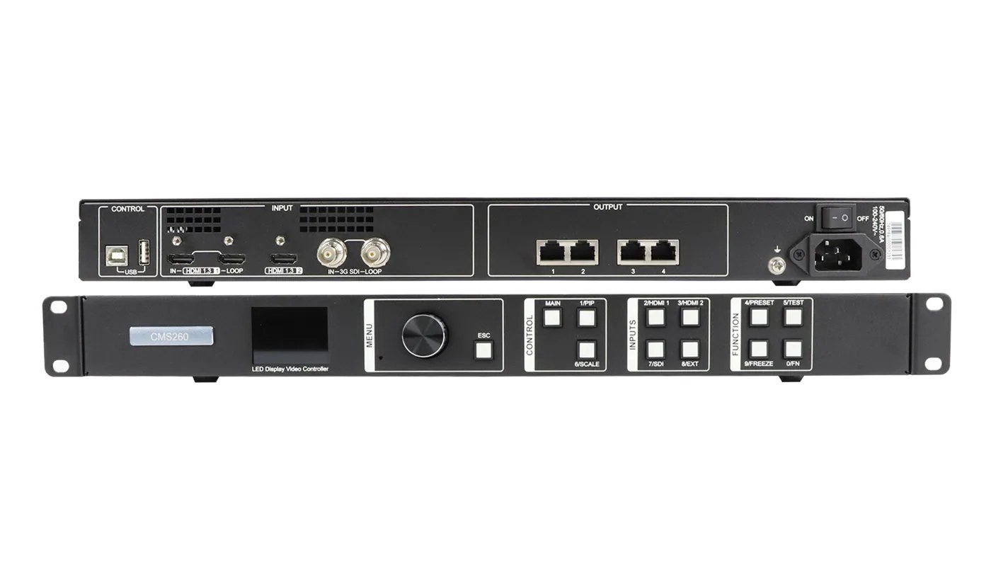
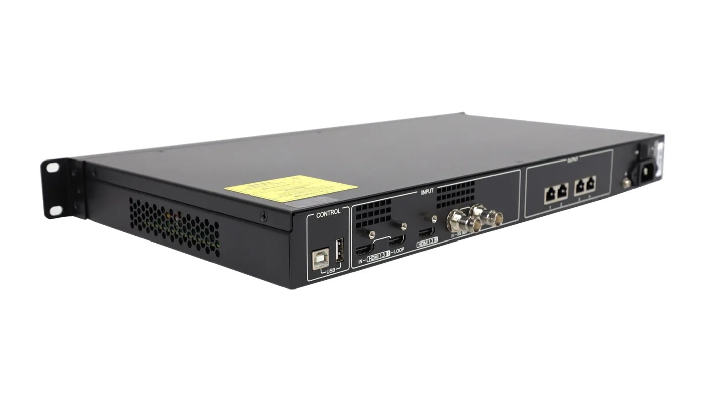
| Video inputs | HDMI 1.3, DVI-D, VGA and CVBS | Two HDMI 1.3 inputs and one 3G-SDI input | Every source connector and accepted format |
| USB role | Type-A media input; Type-B computer updating/debugging | Type-B computer/cascade input; Type-A cascade output | Do not infer flash-drive playback from socket shape |
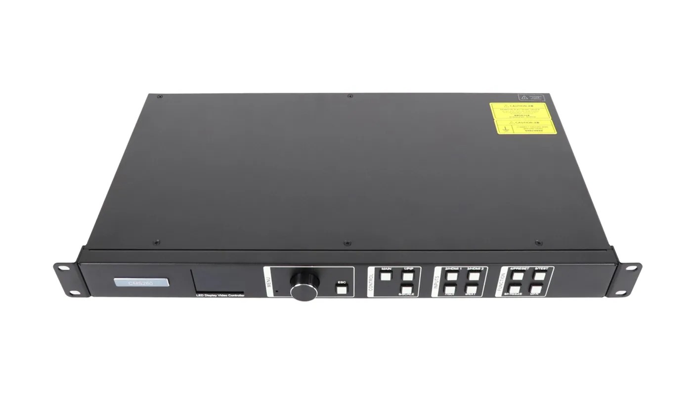
| Layouts and presets | Scaling, layer positioning and cropping; six presets | Two layers with adjustable priority; ten presets | Required layout and recall workflow |
| Audio path | Separate audio input and output connectors | HDMI audio input; multifunction-card output through Ethernet port 1 | Required supporting hardware and routing |
Use the CMS130 product specifications and CMS260 product specifications to review connector details. Check current availability and the supplied revision on the product page rather than using a price copied into a long-lived guide.
This CMS130 vs CMS260 table deliberately separates supported features from suitability. A controller can provide the right connector and still reject the source format. Likewise, a screen below a total pixel limit can still require a different port map.
3. Check Input Timing, Bit Depth and Scan Type
Matching HDMI connectors does not establish equivalent HDMI support. The two published specifications describe different bit-depth and interlaced-input conditions.
01. Verify the CMS130 source format
The CMS130 listing documents HDMI and DVI inputs up to 1920 × 1080 at 60 Hz, with interlaced input supported. Its HDMI format table includes 8-bit and 10-bit RGB 4:4:4, YCbCr 4:4:4 and YCbCr 4:2:2. It excludes 12-bit HDMI and YCbCr 4:2:0. The DVI table specifies 8-bit RGB 4:4:4.
If a source can output several formats, record the intended setting rather than merely writing that it is a 1080p device. Keep a tested fallback format in the commissioning notes. In the CMS130 vs CMS260 comparison, accepting a source at one bit depth does not prove acceptance at another.
02. Verify the CMS260 source format
The CMS260 HDMI specification lists 8-bit RGB 4:4:4, YCbCr 4:4:4 and YCbCr 4:2:2. It excludes interlaced HDMI, 10-bit and 12-bit HDMI, and YCbCr 4:2:0. Documented HDMI examples include 1920 × 1200 at 60 Hz, custom 3840 × 600 at 60 Hz, and forced 600 × 3840 at 60 Hz.
The 3G-SDI input supports up to 1920 × 1080 at 60 Hz and deinterlacing, but the published document excludes Level B. A project needing an SDI camera source should therefore identify the camera’s actual output standard, not only the presence of an SDI connector.
A useful CMS130 vs CMS260 specification review attaches a source-format sheet to the controller request. For an unfamiliar source, ask for confirmation of the exact timing and format before treating a proposed adapter or conversion chain as approved.
4. Decide Whether You Need USB Playback or Live Layers
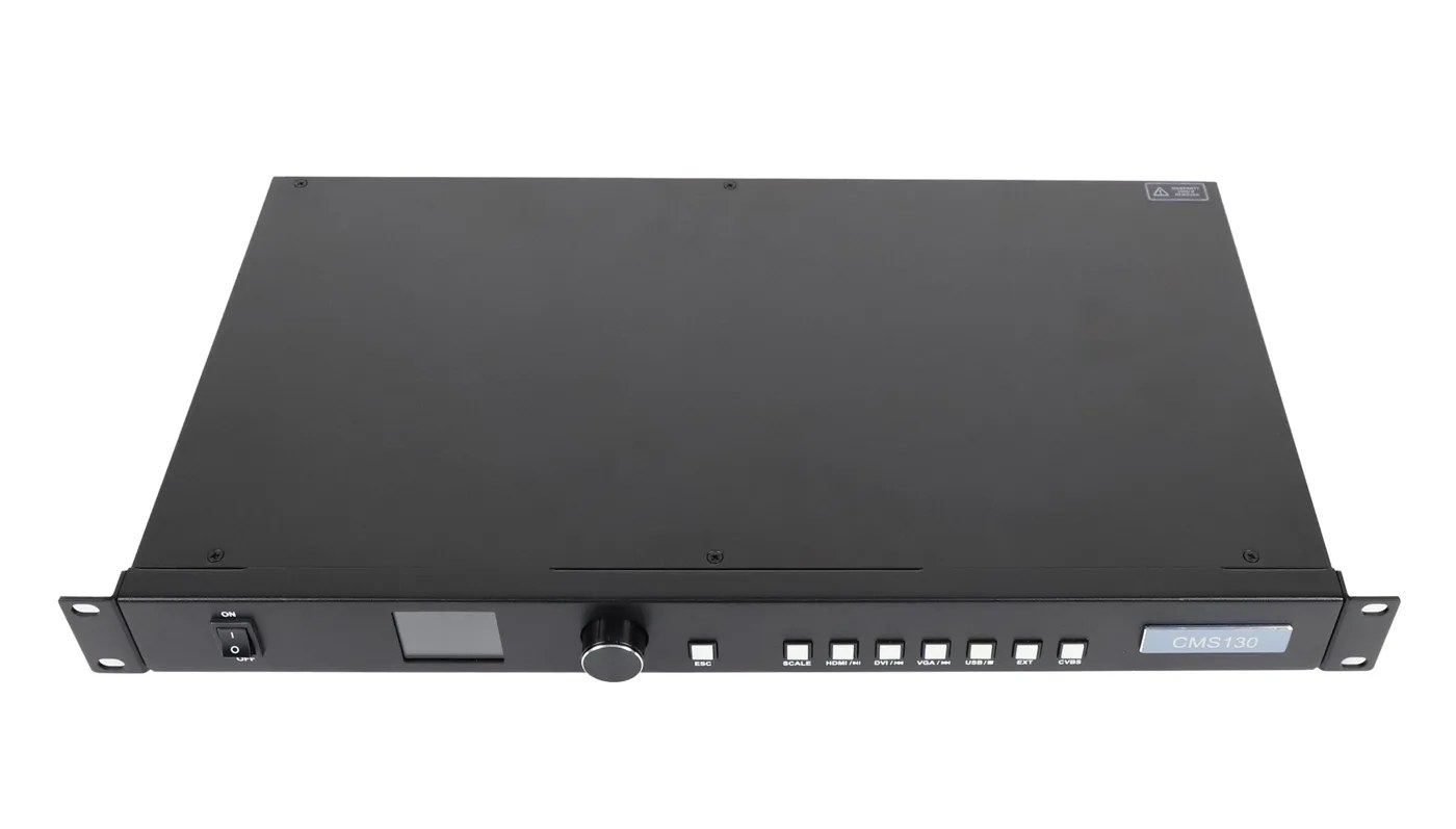
The CMS130 has documented USB media playback, whereas the CMS260 USB connections serve computer control and cascading in the retained specification. A USB connector is not a generic media-player guarantee.
The CMS130 Type-A input supports video files up to 1080p at 30 fps. The listed file systems are NTFS, FAT32 and FAT16; exFAT is excluded. Still-image formats include JPG, JPEG, PNG and BMP. File extension, codec, resolution, frame rate and drive format should all be checked together.
Prepare a representative media file before installation and test it using the actual drive and controller. A codec family appearing in the specification does not make every export profile suitable. Keep the approved export settings with the project so future content does not introduce a different format.
For the CMS260, plan an appropriate external source when the job requires stored video playback. Its Type-A cascade connection should not be specified as a flash-drive input. That distinction can be more important than total pixel capacity in a CMS130 vs CMS260 purchase.
The CMS260’s two layers support a main image and picture-in-picture layout with adjustable size, position and priority. Describe the required layout using a drawing and source list. Identify which image must stay visible during changes, and validate the intended preset behavior during commissioning.
Neither model should be selected on a vague request for more features. In CMS130 vs CMS260 planning, a single-source sign with legacy inputs and a presentation display with a camera inset represent different workflows, even at the same screen resolution.
5. Review Output Mapping, Backup and Audio as a System
Total output capacity does not replace a cabinet-by-cabinet connection plan. Record the pixels assigned to each LED output, the receiver order and the intended behavior of any backup connection.
The CMS260 specification identifies device, Ethernet-port and input-source hot backup. Those terms describe different failure cases. A spare input source does not replace a failed output cable, and an output backup does not establish that the source will continue to provide valid video.
Ask the integrator to document the failure each proposed backup addresses, the required connections and the acceptance test. Do not count backup ports as additional independent display capacity without a supported topology. The CMS130 vs CMS260 choice should be made against the normal and backup operating arrangements.
Audio needs its own review. The CMS130 has separate audio input and output connections. The CMS260 uses HDMI audio input and documents multifunction-card audio output through Ethernet port 1. Confirm the relevant card, cabling and route if the display installation includes sound.
Keep central control and LED data separate in the cable schedule. The CMS130’s connector labeled ETHERNET (RS232) serves central control; it is not another LED output. Numbering every socket in a drawing is more useful than asking site staff to connect a cable to whichever network-style port is free.
For either model, retain the receiving-card configuration and the screen connection record. If an existing cabinet is being repaired, the receiving-card replacement checklist explains the information needed before changing receiver hardware.
6. Use an Acceptance Checklist Before the Installation Date
A CMS130 vs CMS260 purchase should end with a defined validation plan. Specify what successful operation looks like before the controller is installed, then record the result for each source and display mode.
| Test | Record | Reason |
|---|---|---|
| Source acceptance | Connector, timing, scan type, bit depth and color format | Distinguishes a source-format problem from a wall problem |
| Screen mapping | Output number, receiver order and cabinet pixels | Makes the approved connection arrangement reproducible |
| Scaling or crop | Input area and intended displayed area | Confirms that important image content is visible |
| Layout recall | Preset name, source assignments and image positions | Helps operators restore an approved presentation |
| Backup, if required | Failure simulated, alternate path and observed recovery | Tests the actual redundancy requirement |
| Restart | Stored configuration and normal startup result | Checks persistence separately from temporary operation |
Perform these checks with representative content, not just a uniform test color. A wall can show a test pattern while displaying a live source with the wrong crop or aspect ratio. Include readable text, edge markers and the intended layout in the acceptance material.
The CMS130 vs CMS260 decision also includes installation constraints. The listed chassis dimensions are 482.6 × 250.0 × 50.0 mm for CMS130 and 482.6 × 250 × 50.1 mm for CMS260, approximately 19.0 × 9.84 × 1.97 in. Confirm mounting clearance, cable access and ventilation against the supplied hardware.
The retained specifications list 100–240 V AC input for both units, with rated consumption of 12 W for CMS130 and 28 W for CMS260. These are controller figures, not LED-wall power consumption. Have the installation’s power arrangement checked for its actual equipment and location.
Keep one change record for the final accepted setup. Record the controller identity, software or firmware information available, source settings and approved files. This makes a future CMS130 vs CMS260 reassessment traceable if the customer later adds a camera, changes the wall or replaces the playback source.
7. Write a Purchase Specification That Explains the Choice
The final CMS130 vs CMS260 specification should describe the approved source and operating requirement, not just a model number. This lets purchasing identify whether an offered substitution changes a function the installation needs.
Consider a hypothetical information display that must accept an existing VGA source and play prepared video from a USB drive. The first questions are whether the source timing is accepted and whether the USB files meet the CMS130 limits. Unused LED capacity on a CMS260 would not create the missing VGA input or documented USB media function.
By contrast, consider a hypothetical presentation installation with an HDMI computer source and a compatible 3G-SDI camera feed, where the operator needs a main image and an inset. That request directs the review toward the CMS260’s documented input and two-layer arrangement. The integrator must still validate the source formats, layout and wall map.
These are decision examples, not completed customer projects. They show how a CMS130 vs CMS260 review can reach different shortlists without declaring one controller universally better. The actual wall resolution and supported receiver configuration remain necessary in both cases.
Write a separate line for each mandatory input. Identify the connector and the expected video format, then name any conversion equipment required. If a source supplier changes the camera or computer output later, that line identifies which part of the acceptance test must be repeated.
Next state the exact screen pixel dimensions and attach the approved LED output map. Avoid a purchase line that contains only a maximum pixel number. Cabinet arrangement, receiver order and source preparation can matter even when the total load remains unchanged.
For stored playback, attach the tested export profile and drive-format requirement. Include the normal procedure for changing content and returning to the accepted program. If an external player is required, list it explicitly so it does not disappear between the controller quotation and installation.
For layouts, identify the number of simultaneous images, their source assignments and the presets staff actually need. Six or ten available preset slots do not define the operational plan by themselves. A short list of named, tested layouts gives the operator something concrete to recall.
For audio, name the full route and any supporting multifunction card. Specify which connection delivers sound and where it is tested. A successful silent video demonstration should not be accepted as evidence that a separate audio requirement has been completed.
Finally, state who retains the final files and source settings. Include a startup check and a recovery procedure appropriate to the approved configuration. These records do not need to be lengthy, but they should identify the unit, the operating mode and the last accepted settings.
A change-control note is useful when the customer expects future additions. For example, adding an SDI source, changing bit depth or expanding the wall should trigger a fresh format and capacity review. It should not be treated as a minor cable substitution simply because the existing display still powers on.
This specification turns the CMS130 vs CMS260 choice into a reviewable requirement. LED Mall can then compare the offered hardware with the source list and connection plan, while the integrator can verify that the installed system matches the original purchasing decision.
Frequently Asked Questions
Keep the CMS130 vs CMS260 review with the project files so the purchasing decision can be checked when a source or screen changes. The comparison is most useful when each required function has an identified source, connection and acceptance record.
Can a lower-resolution source fill the entire LED wall?
Both product descriptions include scaling functions, but the source and output requirements still need review. Confirm the intended crop, aspect ratio and accepted input format. Scaling an image does not add source detail or raise the controller’s LED loading limit.
Can I reuse an existing controller configuration on a new wall?
Keep the old file as a reference, but verify the new cabinet pixels, receiver configuration and output map. A new wall with different modules or wiring should not inherit settings solely because its physical dimensions look similar.
Should I buy CMS260 simply to allow future expansion?
In a CMS130 vs CMS260 review, define the expansion first. Additional pixels, SDI input and a second layer are separate needs. A future legacy source might still require conversion even when unused pixel capacity remains.
Does a loop output create another independently controlled wall?
Do not assume that it does. A loop connection passes the associated signal according to the device’s documented behavior. Independently controlled displays need a reviewed source and output arrangement, including synchronization where required.
Can my operator use a phone instead of the documented control workflow?
Do not assume mobile control from a general reference to network connectivity. State the required operator device and control method in the inquiry, then confirm supported software and connections for the supplied controller.
Turn the Comparison Into a Controller Request
For a stored-content workflow, review AD20 playback modes. If the system needs a separate sending controller or optical path, use the MCTRL signal-chain comparison to define the remaining equipment.
Send LED Mall the screen resolution, cabinet arrangement, source-format list, required layouts and any audio or backup requirement. Review the two product pages and request a CMS130 vs CMS260 compatibility check for that configuration. Keep unresolved source or mapping questions visible until the complete signal chain has been reviewed.