
LEDMall Blog
Why Are NovaStar CVT10 Ports 9 and 10 Unavailable?
Nov
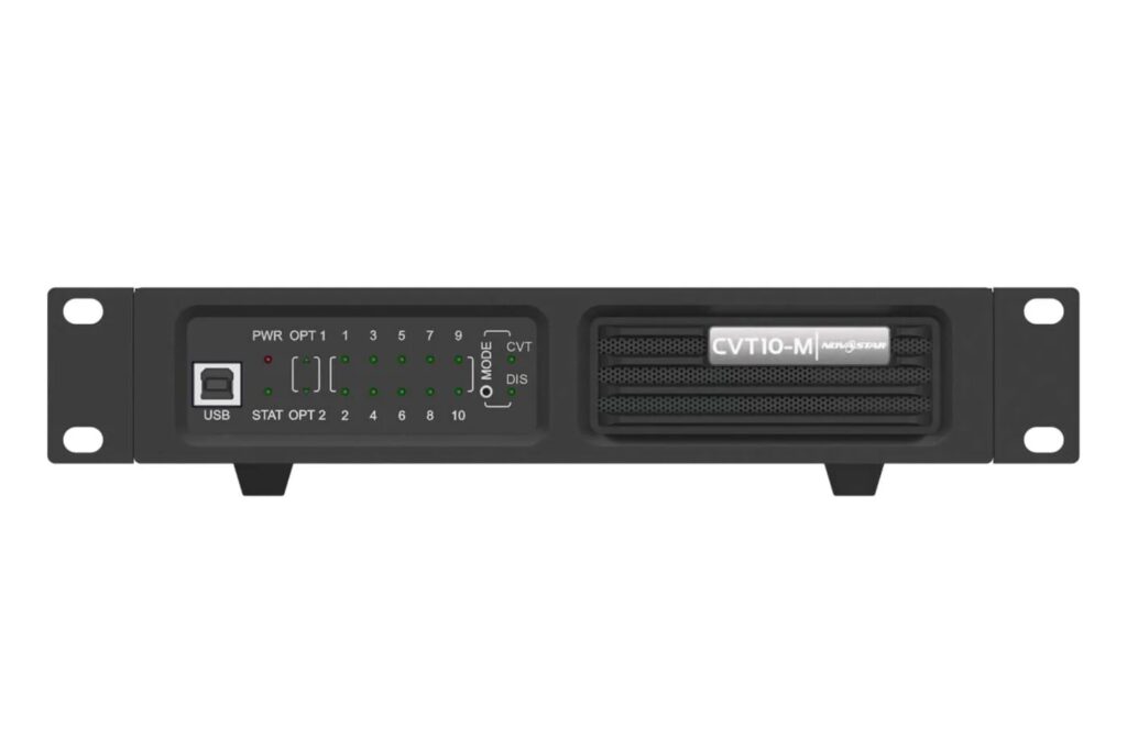
CVT10 ports 9 and 10 can be unavailable because usable Ethernet-port count depends on the connected sending equipment and conversion direction. In the retained V1.2.2 specification, fiber input from an eight- or sixteen-port device makes the first eight CVT10 Ethernet ports available; a ten- or twenty-port device supports all ten. Confirm the sender and firmware before diagnosing two unused ports as a hardware fault.
This guide is for an LED screen maintenance technician investigating the last two Ethernet ports on a CVT10-S or CVT10-M. It explains one diagnostic question, rather than treating every dark status light as a reason to buy another converter.
The references are the CVT10 specifications V1.2.2, dated May 31, 2021, and the model-specific product notes. The document’s future-upgrade wording does not prove that an enabling update is available for every installed system.
CVT10 Ports 9 and 10: Identify the Conversion Direction
The first diagnostic question is whether the CVT10 receives fiber and outputs Ethernet, or receives Ethernet and outputs fiber. The retained specification gives different port-availability rules for those directions.
Write down the equipment connected at each end and which connection carries the incoming display data. A list containing only the converter model and a fiber cable is insufficient to establish the route.
| Conversion direction | Connected equipment condition | V1.2.2 availability statement | Next check |
|---|---|---|---|
| Fiber input, Ethernet output | Input device has eight or sixteen Ethernet ports | First eight CVT10 Ethernet ports available | Verify sender mapping before suspecting ports 9 and 10 |
| Fiber input, Ethernet output | Input device has ten or twenty Ethernet ports | All ten available, with a future-upgrade caveat if ports 9 and 10 are unavailable | Confirm supported programs and installed firmware |
| Ethernet input, fiber output | Documented reverse-conversion arrangement | All ten Ethernet ports available | Check the complete supported topology and signal route |
Do not generalize those historical categories to every newer sending device without confirmation. Provide the exact controller model, operating mode and software information when requesting a review of CVT10 ports 9 and 10.
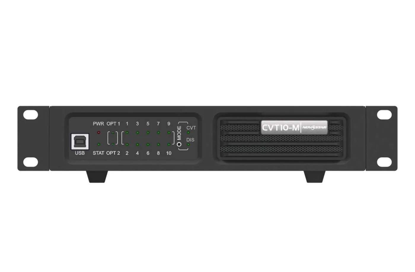
The CVT10-M product notes and CVT10-S product notes explain the conditions associated with the retained specification.
Check the Sender’s Mapping Before Replacing Hardware
A port without assigned or supported data is not proof of a failed connector. Verify the sender’s intended output mapping and the supported converter arrangement before ordering a replacement.
Record which Ethernet outputs are expected to carry cabinet data and how that data reaches the optical link. Identify the first cabinet on each intended branch, its receiver model and the observed symptom. Keep primary and backup paths clearly labeled.
If CVT10 ports 9 and 10 are unused under the documented sender condition, moving a cabinet chain to those sockets does not create a valid additional output. A revised topology must be supported by the complete system, not just by the physical presence of two empty RJ45 connectors.
When the required arrangement should support all ten ports, check the actual firmware and programs against the applicable documentation. Preserve the existing configuration and ask for a model-specific procedure before applying an update. Do not install an unrelated package because another converter has a different version string.
A known-good cable and a verified compatible cabinet branch can help isolate a fault, but change one variable at a time. Record whether the symptom follows a cable or stays with the same supported output. Follow the equipment’s service instructions and have qualified personnel handle internal or power connections.
Keep Optical Backup Separate From Extra Output Capacity
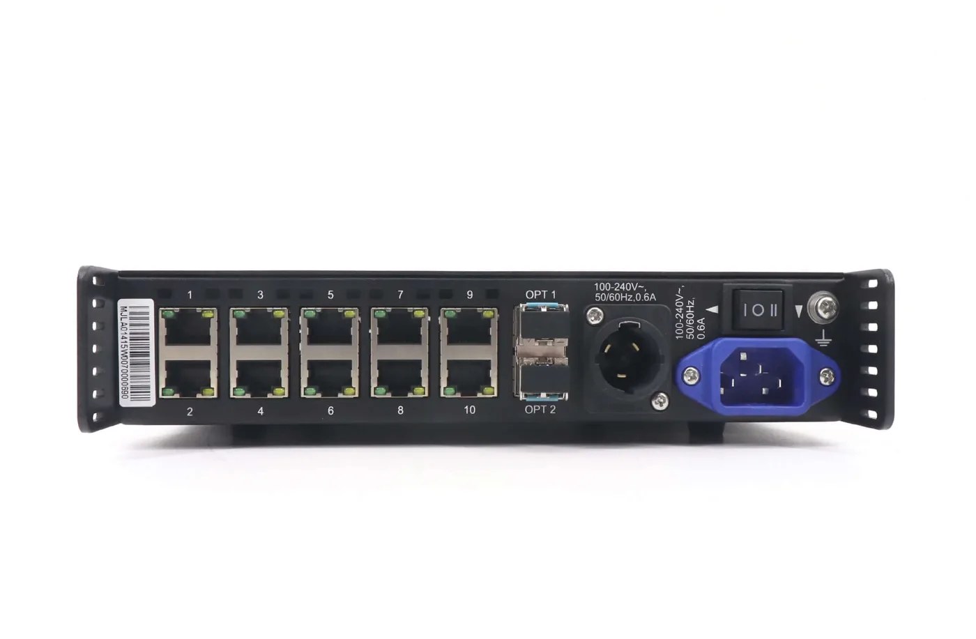
The two optical ports have documented primary and backup roles in CVT mode. They should not be treated as two independent groups of ten Ethernet outputs.
In the retained V1.2.2 description, OPT1 is primary and OPT2 is backup. CVT is the supported default mode, while DIS is reserved. A reserved label is not an enabled distribution feature.
This distinction matters when diagnosing CVT10 ports 9 and 10 because an assumed extra optical data group can create an incorrect output plan. Draw the supported primary route and backup route before assigning cabinets.
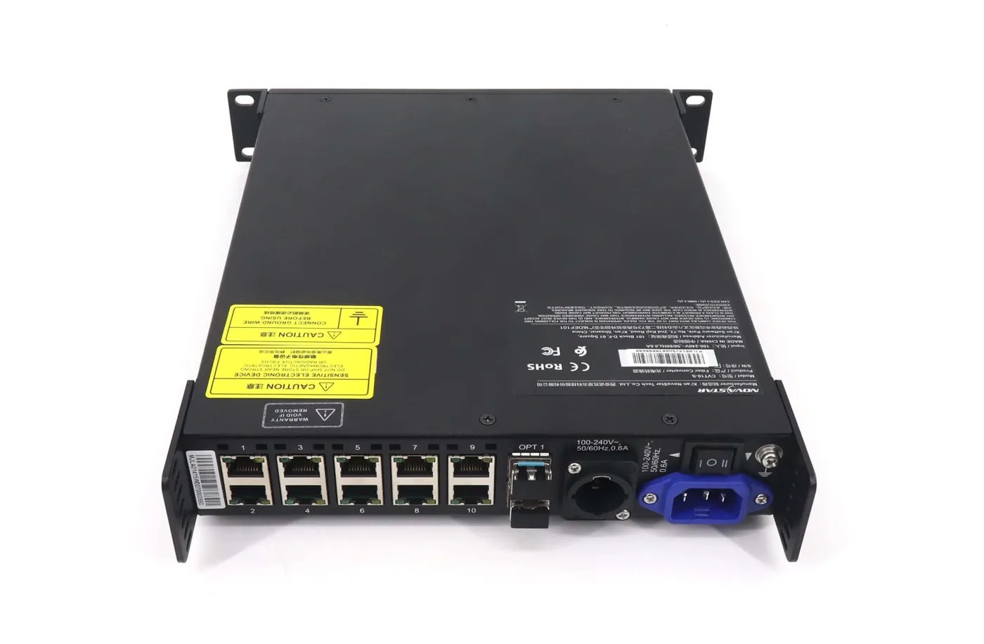
Also keep the optical model and fiber type together. CVT10-M is documented at 850 nm with OM3/OM4 multimode twin-core fiber, 50/125 μm, LC connectors and a specified 300 m distance, approximately 984 ft. CVT10-S is documented at 1310 nm with OS1/OS2 single-mode twin-core fiber, 9/125 μm, LC connectors and a specified 10 km distance, approximately 6.2 miles.
Those are specified optical arrangements, not guarantees for an unmeasured installed route. Confirm the equipment, modules, fiber and loss requirements at both ends. Correcting an unsuitable fiber arrangement is a different task from determining whether the sender makes the last two Ethernet ports available.
Use Indicators to Describe the Fault Precisely
Indicator observations are useful evidence when tied to the actual signal path. Record what the converter shows before changing connections, then compare that observation with the applicable manual.
The CVT10 front panel provides power, running, optical and numbered Ethernet indicators. Note whether the converter is powered, whether its normal running indication is present, which optical connection is active and which numbered Ethernet connections have the expected status.
For CVT10 ports 9 and 10, include photographs showing the front indicators and rear connections. A report saying that the last ports are dead leaves out whether the sender condition supports them and whether the expected data reaches the converter.
The Type-B USB connection is documented for program upgrades from a computer using NovaLCT V5.4.0 or later, not for cascading converters. Do not add a USB cable between units to create an unverified data route.
The document also distinguishes hot-swappable optical modules from the PowerCON connection, which must not be connected while live. Follow the specified handling procedure; a hot-swappable optical part does not make every connector safe to move under power.
If a receiving-card branch also needs investigation, preserve its identity and settings. The receiving-card replacement checklist helps distinguish cabinet-side evidence from a converter-port availability question.
Keep a before-and-after record if a supported program change is made. Identify the package, the equipment configuration and the port test that was repeated. A changed version number alone is not evidence that CVT10 ports 9 and 10 now carry the intended cabinet data. Confirm the actual output behavior and retain the final mapping with the installation files.
Frequently Asked Questions
Does the future-upgrade note mean I should update immediately?
No. It identifies a condition in a historical specification, not an approved package for your installation. Confirm the sender, converter and supported program combination, then obtain the appropriate procedure if an update is required.
Can I replace CVT10-M with CVT10-S to activate the last ports?
Changing between multimode and single-mode models is an optical-system change, not an automatic solution for output availability. The sender and conversion-direction rules still need review, while the fiber and optical modules must match the selected model.
Can a normal computer-network switch provide extra LED outputs?
Do not assume that a general-purpose network switch can expand the supported LED data arrangement. Obtain a reviewed topology using compatible equipment. The appearance of standard Ethernet connectors does not establish a supported distribution method.
What evidence is needed before returning a converter?
Provide model and revision information, sender identity, conversion direction, port mapping, indicator photographs and results from controlled cable or branch checks. That evidence helps separate unsupported routing, configuration and an actual hardware fault.
Send the Topology With the Port Report
For the upstream equipment, review the MCTRL signal-chain guide. At the receiving end, the DH cabinet-output comparison helps keep converter Ethernet ports separate from the module connections inside each cabinet.
For a CVT10 ports 9 and 10 inquiry, send the sender model, converter model, firmware information, optical direction and cabinet-output map. Add front and rear photographs and identify the exact expected behavior. Ask LED Mall to review the converter arrangement before purchasing another unit.