
LEDMall Blog
How to Choose a Replacement Receiving Card for Your LED Screen
Nov
A replacement receiving card must match your LED screen’s control system, module wiring, driver IC, scan mode, cabinet resolution and saved configuration. Choose the exact original model and revision when available, then confirm the electrical and mechanical fit before ordering. A matching connector or a higher pixel capacity alone does not establish compatibility.
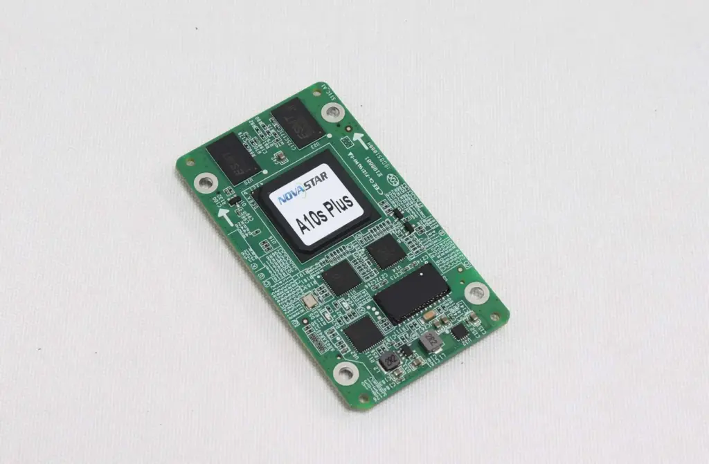
This guide is for LED screen maintenance technicians selecting a replacement receiving card for an existing installation. It explains what to record, what to rule out before buying hardware, and how to compare NovaStar A8s Pro, NovaStar A10s Plus and Colorlight 5A-75B listings without assuming they are interchangeable.
Keep the working screen’s settings and cable map intact throughout the repair. If the original module or cabinet documentation is missing, collect clear photographs and request a compatibility review before selecting a different model.
1. Identify the Original Before Choosing a Replacement Receiving Card
Start with the label and board revision on the installed card, rather than the screen’s marketing name. The same cabinet size or pixel pitch does not tell you which receiver, HUB board or configuration the manufacturer used.
01. Photograph the complete signal path
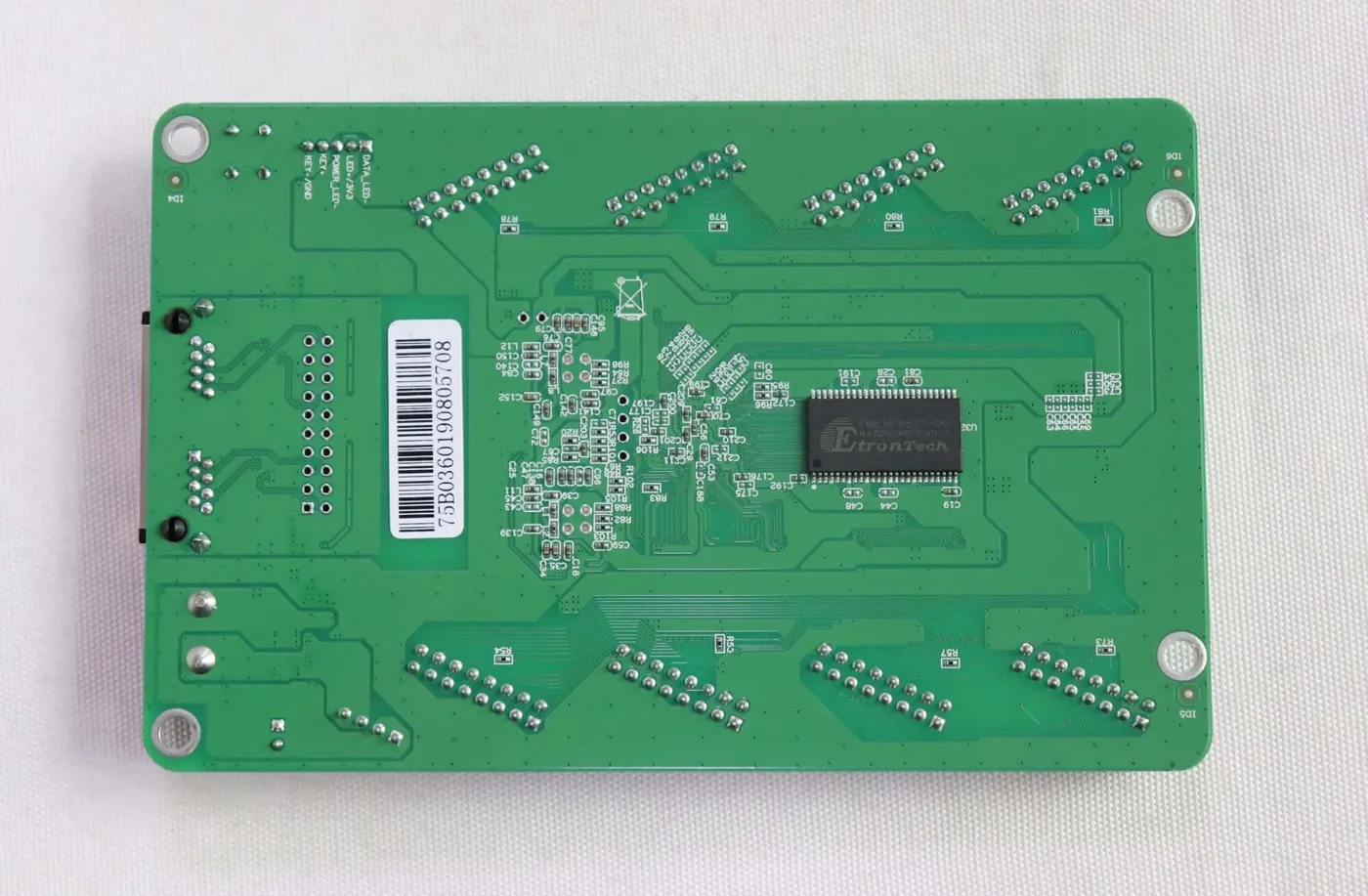
Take a readable photograph of the card label, both board faces, its power connection and the module-side connectors. Include the HUB board if the receiver plugs into one. Record the sending controller’s full model name and photograph the module’s rear label, driver IC markings and ribbon-cable routing.
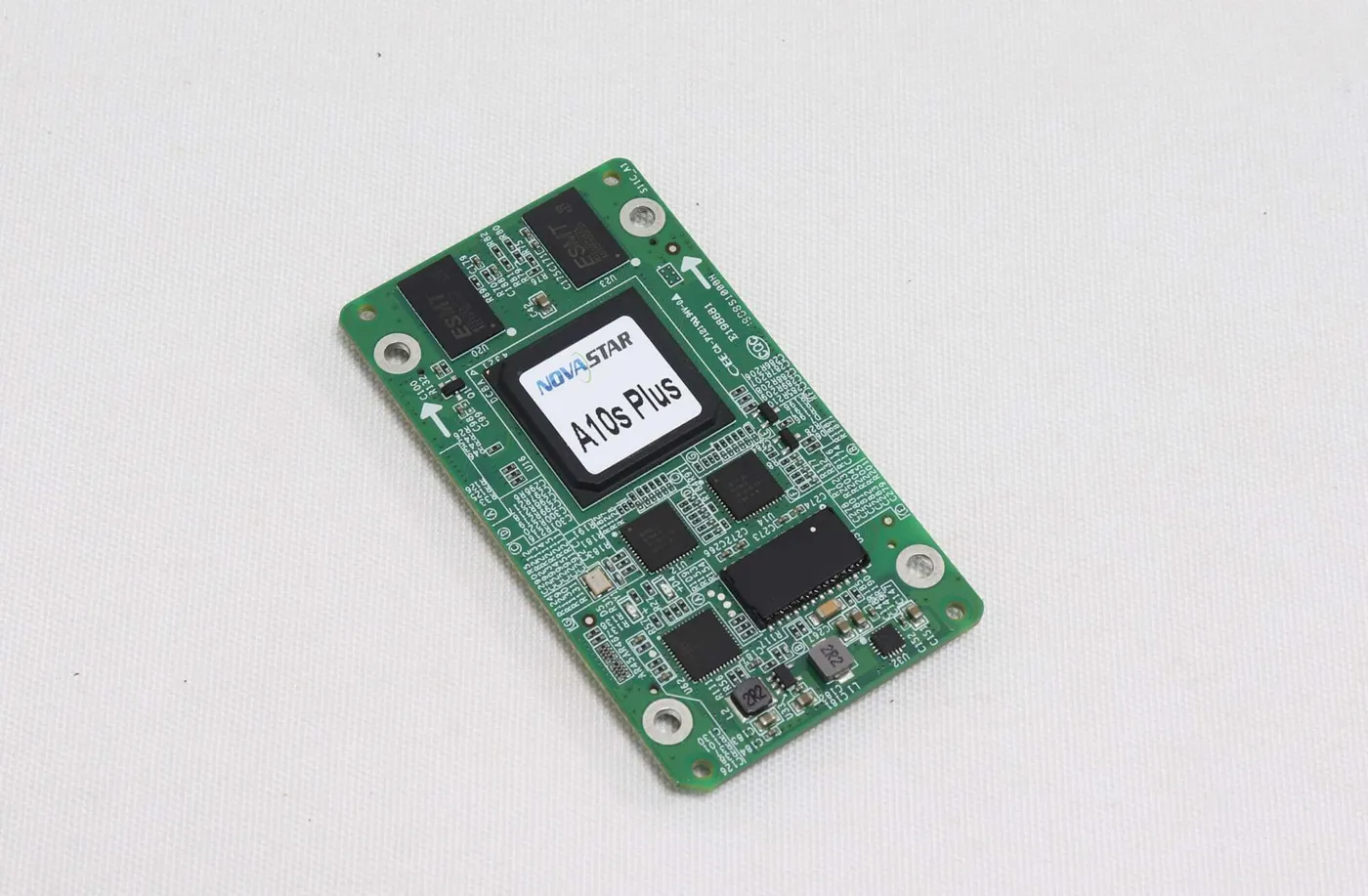
A replacement receiving card request should preserve suffixes such as Plus, Pro, S or N exactly as printed. Do not shorten A10s Plus to A10s or treat A8s and A8s Pro as the same item. Board labels, connector placement and documented revision differences are more useful than a visually similar online thumbnail.
02. Record one working cabinet as a reference
If an identical cabinet still works, document its card, firmware, module arrangement and position in the data chain. Save the available configuration before disconnecting anything. Confirm that this reference cabinet really uses the same module batch and wiring; a neighboring panel with a different internal layout is not a reliable template.
Keep photographs with the job record and label the original cables before removal. A simple cabinet identifier, controller output number and receiver position can prevent a correct repair from becoming a mapping problem later.
2. Check Whether the Receiving Card Actually Needs Replacing
A dark cabinet or distorted image is a symptom, not proof of a failed receiver. Check power, signal continuity, module connections and configuration before purchasing a replacement receiving card.
Have a qualified technician isolate power before moving boards or reconnecting internal wiring. Follow the cabinet’s service procedure and use appropriate antistatic handling. Do not open a mains power supply or move energized connectors as part of a quick comparison.
| Observed symptom | Check first | Evidence to collect before ordering |
|---|---|---|
| One whole cabinet is dark | Cabinet DC supply, receiver power connection and upstream data path | Measured supply condition, status indicators and controller detection result |
| A chain of downstream cabinets is dark | First affected cabinet, incoming cable and preceding output connection | Exact point where communication stops; results with a known-good cable |
| Only one module or ribbon-cable branch is wrong | Module power, ribbon orientation, connector and HUB output | Whether the fault follows a verified compatible cable or module |
| Repeated blocks, wrong colors or scrambled rows | Module parameters, scan settings and cabinet mapping | Configuration file version and whether the fault began after a settings change |
| Correct image until the next restart | Whether settings were saved to hardware using the applicable procedure | Before-and-after restart photographs and the saved configuration record |
Change one variable at a time and keep a written result. For example, a known-good signal cable can help isolate the data path, but swapping a controller, cable and receiver together makes the result hard to interpret. Use comparison parts only after confirming their compatibility.
A replacement receiving card becomes a reasonable next step when these checks isolate the fault to that board, or when the original board is visibly damaged and the surrounding cause has been addressed. If the power source caused the failure, installing another card without correcting that source can repeat the damage.
3. Check the Six Compatibility Conditions Before Ordering
Compatibility is a chain of requirements: controller support, physical interface, electrical supply, module driving, loading limits and configuration. Your replacement receiving card needs to satisfy all six, even when its advertised capacity exceeds the original.
01. Match the control-system family and supported combination
Identify the sender or video controller before comparing receivers. A cable with an RJ45 connector does not establish that two LED control systems use the same receiving protocol. Do not assume a Colorlight receiver will operate on an existing NovaStar output, or that changing brands is a one-board repair.
A cross-brand conversion requires review of the controller, receivers, module interface and software configuration as a complete system. For routine maintenance, keep the existing supported architecture unless the cabinet supplier has confirmed a different combination.
02. Check HUB connections, power and board fit
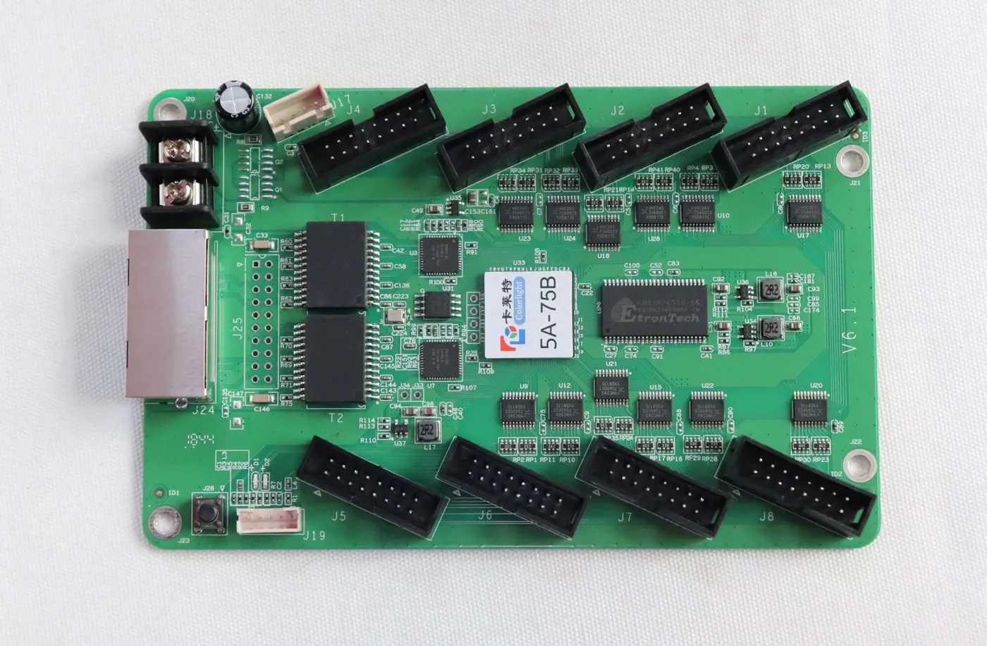
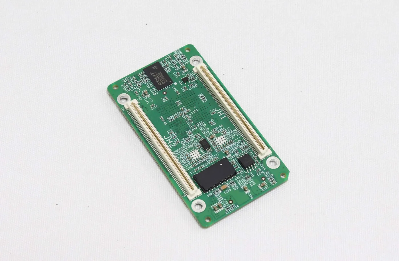
Compare connector type, pin assignment, orientation, mounting holes and available clearance. A receiver with high-density HUB-board connectors has a different integration path from a board with direct HUB75 sockets. An adapter is not evidence that the resulting pinout and signal routing are correct.
Check the input-voltage range for the exact model and revision, the power connector and polarity, and the cabinet supply arrangement. A replacement receiving card should be selected against the installed circuit and official wiring information; never infer polarity from a wire color or a photograph alone.
03. Match the module and its configuration
Record driver IC, decoding arrangement, scan mode, pixel dimensions and module data routing. Matching pixel pitch only establishes the physical spacing of the LEDs. Two P2.5 modules can still need different driving parameters, and identical module dimensions do not guarantee identical wiring.
Finally, verify that the required configuration and firmware are supported by the proposed receiver. The saved settings, hardware model and module arrangement must be reviewed together. Treat missing driver information or an unknown HUB pinout as an open compatibility question, not an invitation to experiment on the live wall.
Two examples show why this review matters. A compact board may offer enough pixels but fail to mate with the installed HUB board. A direct-HUB75 board may appear to fit the ribbon cables while requiring a different supported sender or module parameter set. In either case, the proposed replacement receiving card has passed only one part of the review. Resolve the remaining conditions before planning the repair.
4. Compare A8s Pro, A10s Plus and 5A-75B by Integration Requirements
These three products illustrate different receiver designs, rather than a universal upgrade ladder. The comparison below helps identify which details need checking; it is not a replacement receiving card approval chart.
| Model and source revision | Published loading and outputs | Physical and electrical checks | Replacement decision |
|---|---|---|---|
| NovaStar A8s Pro; specifications V1.1.0 | Up to 512 × 512 pixels at 60 Hz; up to 40 parallel RGB groups or 64 serial groups | High-density connectors; 70 × 45 mm board footprint; DC 3.8–5.5 V input | Confirm the existing HUB board, module configuration and supported controller |
| NovaStar A10s Plus; specifications V1.0.0 and V1.0.3 | Up to 512 × 512 pixels; up to 32 parallel groups or 64 serial groups | High-density connector integration; 80 × 45 mm footprint; DC 3.3–5.5 V input | Confirm Plus model and supplied revision; do not substitute an A10s Pro document |
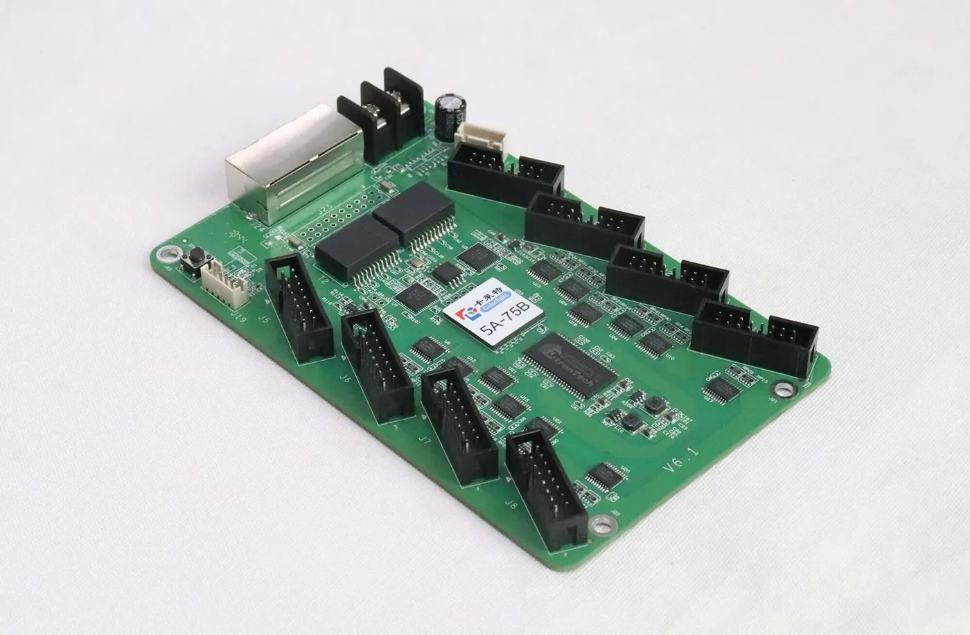
| Colorlight 5A-75B; specifications V8.3.1 | Eight HUB75 interfaces; 16 parallel RGB groups; loading depends on driver-chip type | 145.2 × 91.7 × 18.4 mm; DC 3.8–5.5 V supply | Confirm the Colorlight system, module pinout, scan mode and chip-specific load |
The A8s Pro and A10s Plus footprints are approximately 2.76 × 1.77 in and 3.15 × 1.77 in, respectively. The 5A-75B dimensions are approximately 5.72 × 3.61 × 0.72 in. Use the actual mechanical drawing and mating connectors to confirm fit, rather than these rounded inch conversions.
Review the NovaStar A8s Pro product details, A10s Plus model and revision notes and Colorlight 5A-75B specifications before sending a parts request. The A10s Plus listing identifies its retained A10s Pro download as a different-model reference. Its two Plus revisions also list different overall heights, so confirm the supplied revision if clearance is tight.
For the 5A-75B, the listed control areas are 128 × 1024 pixels for normal chips, 192 × 1024 for PWM chips and 162 × 1024 for Shixin chips. These are conditional figures, not one capacity that can be applied to every module. Ask which specification applies to your installed driver.
5. Calculate Cabinet Pixels Before Comparing Capacity
Calculate the pixels connected to each receiver, then check both width and height limits under the required operating conditions. A total pixel count alone cannot qualify a replacement receiving card.
Here is a hypothetical calculation, not a tested cabinet configuration. Suppose a regular cabinet contains six identical modules, arranged three across and two high. Each module has a confirmed resolution of 128 × 64 pixels:
- Cabinet width: 3 × 128 = 384 pixels.
- Cabinet height: 2 × 64 = 128 pixels.
- Receiver load, assuming one receiver serves the entire cabinet: 384 × 128 = 49,152 pixels.
If twelve identical cabinets use one receiver each, the initial hardware count is twelve receivers. That count does not confirm the controller’s output capacity, cable topology, redundancy design or module compatibility. A design with two receivers per cabinet would need a different count and a documented division of the pixels.
Although the example is below the A8s Pro’s published 512 × 512 at 60 Hz dimensions, that numerical comparison is only a first filter. Module driver support, data groups, scan settings, controller support and HUB-board integration still need confirmation. Do not turn spare numerical capacity into a claim that a receiver will work in an unknown cabinet.
Include the intended input frame rate and display settings in the replacement receiving card request. Frame rate, LED refresh rate and grayscale are different parameters; a listing’s maximum pixel dimensions do not promise every image-quality setting at the same time.
6. Prepare Configuration and Acceptance Checks
A replacement receiving card needs settings that match the actual cabinet, followed by a controlled acceptance test. Preserve the original configuration before fitting a replacement receiving card, and keep module-driving settings separate from the screen’s cabinet-position map.
01. Preserve the files and target the correct cabinet
For supported NovaStar systems, NovaLCT uses receiving-card configuration files such as .rcfgx or .rcfg. The NovaLCT synchronous-system user manual describes sending parameters to all receivers or specified receivers. For a single-cabinet repair, confirm the target address and use an appropriately isolated test arrangement instead of broadcasting unverified settings across the installation.
The available file type and controls depend on the card, firmware and software version. Some models also support NCP workflows. Ask for the approved configuration for the exact hardware; do not rename a file extension or copy another brand’s settings to force an import.
Keep a separate copy of the screen connection map, brightness settings and available calibration records. Module-driving parameters do not by themselves establish the cabinet’s image position or reproduce its calibration. A working display is the reference to preserve, not a reason to overwrite every connected board.
02. Test, save and restart
After the mechanical and electrical checks pass, have the technician configure one matching cabinet using the applicable manufacturer procedure. Confirm communication, module orientation, full cabinet coverage, solid colors and a recognizable mapped image before connecting the repaired cabinet to the full display.
For a replacement receiving card, acceptance should include correct image position, stable behavior at the intended settings and retention after a controlled restart. Save settings to the hardware using the supported procedure; saving a file on the service laptop is a different operation.
If the repaired cabinet looks different from its neighbors, compare calibration availability and brightness or color settings before declaring the board defective. Keep the test results and final approved files with the job record so the next repair starts with known information.
Define acceptance before starting the test. Record the cabinet identifier, image source, operating settings and expected module arrangement. Then note whether each module displays the correct area, whether text crosses cabinet boundaries correctly, and whether the repaired cabinet behaves like its verified reference. These observations distinguish successful communication from a complete repair.
For intermittent faults, record the conditions in which the original symptom appeared and repeat the relevant checks under those conditions within the manufacturer’s operating limits. A brief solid-color test cannot establish long-term reliability. If the symptom returns, preserve the evidence rather than changing several settings at once. The acceptance record should say exactly what was checked, without presenting an unmeasured service life as a result.
7. Build a Replacement Receiving Card Request That Can Be Checked
A useful replacement receiving card inquiry contains enough evidence to review the installed system. Send the original model and revision, controller model, both board photographs, HUB details, module label, driver IC, scan mode and cabinet pixel dimensions.
Add the configuration filename, software and firmware versions when available, the fault-isolation results and the quantity required. Explain whether you need a like-for-like service spare or are considering a different model because the original is unavailable.
Ask for confirmation of the proposed model, supplied revision and any required HUB board or configuration work. Check the current product-page price and availability when ordering. The LED Mall buying guide explains the site’s cart and checkout process; resolve compatibility questions before adding hardware for the repair.
You can organize a replacement receiving card request into three short parts. First describe the installation: controller, cabinet pixels, module layout and receiver model. Next describe the evidence: fault location, power and cable checks, and the approved files available. Finally state the decision needed: an exact-model spare or a reviewed alternative, the number of cards, and any mechanical restrictions.
Separate confirmed facts from unknowns. For example, write that the cabinet uses an identified A10s Plus, but that the board revision or module driver has not yet been read. This gives the reviewer a precise question to resolve. Writing only that you need a more powerful card leaves the original fault, interface and configuration unspecified.
When the original is unavailable, request a written list of the changes needed for the proposed replacement receiving card. That list may include a compatible HUB board, an approved configuration and a validation plan. If those requirements cannot be confirmed, pause the substitution and identify the existing cabinet more fully.
Frequently Asked Questions
Can I order a receiving card using only the cabinet’s serial number?
Send the serial number if available, but include the card and module photographs too. A serial number is useful only when someone can connect it to a reliable cabinet build record. Without that record, the internal hardware and configuration still need identification.
Should I keep a spare card already configured?
A labeled spare with an approved configuration can simplify future service. Record the cabinet type, card revision, firmware and file version, and verify the spare in a matching cabinet before storing it. Keep the original files separately so a mislabeled spare does not become the only reference.
Does buying the same model guarantee identical color?
No. Color matching also depends on the modules, calibration coefficients and display settings. Ask how the installation’s calibration records will be preserved or restored when a receiver is replaced; the model name alone does not provide those records.
What if I no longer have the original configuration file?
Ask the cabinet supplier for the approved file and check whether readback from an identical working cabinet is supported. If neither route is available, configuration must be established and tested for the actual modules. Do not assume a generic file downloaded for the same pixel pitch is suitable.
Can one replacement receiving card be moved between different screens?
Only after each screen’s hardware compatibility and configuration requirements have been checked. Label the card’s current configuration and preserve the previous files before reassignment. A receiver that works in one cabinet is not automatically a service spare for a different installation.
Get the Right Part for Your Cabinet
Prepare the model labels, board photographs, module information and configuration record before ordering your replacement receiving card. Compare the relevant LED receiving card listings, then contact LED Mall to check the proposed part against your cabinet. Include the quantity and any unresolved wiring or revision questions so those details can be addressed before checkout.