
LEDMall Blog
VX2000 Pro Optical Ports: Copy, Backup and Output Modes

Nov
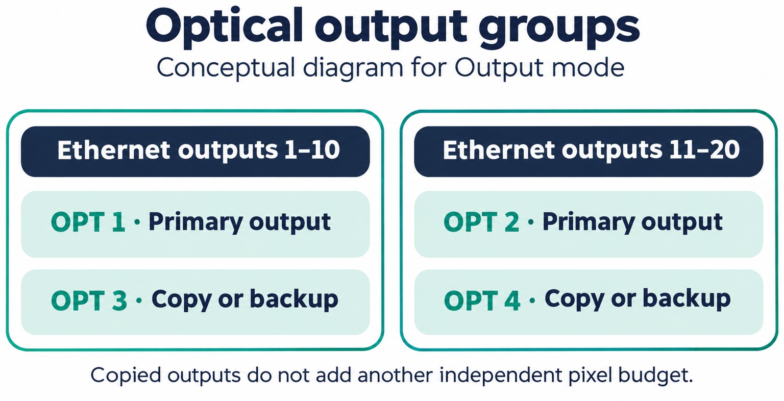
The VX2000 Pro optical ports have different roles depending on the selected optical mode. In Output mode, OPT 1 carries Ethernet outputs 1–10 and OPT 2 carries outputs 11–20. OPT 3 and OPT 4 provide copy or backup for those respective groups. The four physical optical ports therefore should not be counted as four additional independent sets of screen outputs.
This explanation is for a rental-system integrator planning the controller-to-screen signal path. It follows NovaStar’s VX2000 Pro All-in-One Controller Specifications V1.0.0, released December 10, 2024, as supplied with the LED Mall product listing. Confirm the documentation and supported modes for the hardware and firmware offered in the quotation.
How the VX2000 Pro optical ports group the outputs
The controller has twenty Gigabit Ethernet outputs and four 10G optical ports. The specification assigns the electrical outputs to two optical groups. Outputs 1–10 belong to the first group, and outputs 11–20 belong to the second. The output, copy, and backup assignments follow those groups.
Begin with a VX2000 Pro controller output map that shows which cabinets each Ethernet output serves. Then identify where the electrical-to-optical route begins and where a compatible device returns the signal to the screen-side connections. Keep the screen allocation and the transport route on the same drawing.
For the VX2000 Pro optical ports, a copied group remains the same output information. It does not create a new independent screen allocation. The specification lists a total device loading capacity of thirteen million pixels. Check the actual loading conditions and operating features separately when calculating what the screen requires.
Write the output group beside each optical path in the system drawing. For example, a path associated with Ethernet outputs 1–10 should remain identifiable as that group at the receiving end. This helps the installer distinguish an output-group mistake from a fiber or module problem when checking the system.
Check the optical mode before assigning connectors
OPT 1 and OPT 2 are adaptive input/output connectors. Their role depends on the connected equipment and the operating arrangement. OPT 3 and OPT 4 are output connectors. A drawing that labels every optical socket simply as “screen output” leaves this distinction unresolved.
| Optical mode | OPT 1 and OPT 2 | OPT 3 and OPT 4 |
|---|---|---|
| Output | Send the Ethernet-output groups | Copy or back up the respective Ethernet-output groups |
| Input + output | Video input | Copy or back up the Ethernet outputs |
| Input + loop + output | OPT 1 is video input; OPT 2 is loop output | Copy or back up the Ethernet outputs |
The VX2000 Pro optical ports must be assigned with that mode in mind. If OPT 2 is being used as a loop output in an input-and-loop arrangement, it has a different job from OPT 2 in Output mode. Confirm the complete route before ordering optical modules, converters, or fiber assemblies.
The table describes optical connector roles. The controller also has overall working modes, including video controller, fiber converter, and ByPass. Keep those terms distinct in a technical inquiry so the supplier can evaluate the intended operating arrangement without guessing which setting the project team means.
Define what copy or backup should accomplish
A specification that supports copy and backup still needs a project-specific wiring and configuration plan. Describe whether the requirement is to duplicate a group to another destination, provide an alternative path, or protect against a defined interruption. These goals should be written into the acceptance criteria before commissioning.
For the VX2000 Pro optical ports, identify both ends of every primary and proposed backup path. Record the receiving-end equipment, its available connections, and the settings responsible for selecting the active route. Ask the supplier to confirm the supported arrangement for the exact equipment combination.
The general Ethernet-port backup explanation is useful when defining the failure boundary. An optical-path requirement should also state which failure is being evaluated. A second cable can be part of a redundancy design, while the complete design and its behavior still need verification.
Use a documented acceptance test with the actual controller, receiving-end devices, configuration, and screen allocation. Record which path is active, the interruption introduced, and the observed result. This article describes the published connector roles and purchasing checks. It does not report a tested failover time or promise uninterrupted output for an unverified system.
Specify the complete fiber route
A quotation for the VX2000 Pro optical ports should identify the controller mode, output group, receiving-end device, optical modules, fiber assembly, connector arrangement, and route length. Confirm compatibility across that complete list. A “10G” label by itself does not settle fiber type, optical-module matching, connectors, or the application supported by the connected device.

Ask which optical modules and accessories are included in the offered package and which are separate. Keep the confirmed item list with the system drawing. This prevents a controller-only quotation from being interpreted as a complete installed fiber solution.
For a rental inventory, label the equipment and cables by their approved role and retain a recoverable copy of the working settings. If another controller, converter, or module is substituted later, compare its documented capabilities before treating it as equivalent. Repeat the relevant acceptance checks for the changed arrangement.
As a planning example, suppose the cabinet map uses Ethernet outputs 1–6 for one screen section and outputs 11–14 for another. The first section belongs to the 1–10 group, and the second belongs to the 11–20 group. Record the unused outputs too. When reviewing a proposed copy path, compare the associated group and its configured screen allocation, rather than counting the number of optical cables connected to the controller.
Keep the control connections distinct from the display-data outputs. The specification also identifies Ethernet connections for computer control and device cascading. Those control connections have a different documented role from the twenty Gigabit Ethernet screen outputs. On a connection drawing for the VX2000 Pro optical ports, label the screen-data group and management connection separately so an installer can identify the intended endpoint without relying on connector appearance.
During handover, retain the drawing that matches the accepted operating mode. If the same rental controller is later reassigned from an optical Output arrangement to an input-and-loop arrangement, review the roles of OPT 1 and OPT 2 again. An old cable label can describe a previous setup accurately while being unsuitable for the new one. Identify the current mode, the connected device at each end, and the approved configuration together.
Frequently asked questions
Can OPT 3 or OPT 4 be used as a video input?
The cited specification identifies OPT 3 and OPT 4 as output connectors. OPT 1 and OPT 2 provide the adaptive input/output roles. Use the documented arrangement for the intended mode when preparing the connection drawing.
Does a copied optical output double the controller’s pixel capacity?
A copy carries the associated output information. Calculate the screen within the controller’s documented total loading capacity and applicable feature limitations. Additional physical paths should not be added as an independent pixel budget.
Is the HDMI monitoring output an optical backup path?
The specification identifies a separate HDMI monitoring output with fixed 1920 × 1080 at 60 Hz output. Identify its monitoring role separately from the screen-data routes and optical backup requirements.
Prepare the signal-path inquiry
Send the cabinet output map, intended optical mode, path length, receiving-end equipment, and required copy or backup behavior. Include the controller and optical-module identification already available on site. Ask LED Mall to review the VX2000 Pro optical ports and accessory requirements so the equipment list and remaining compatibility questions are clear before purchase.