
LEDMall Blog
NovaStar Ethernet Port Backup: What It Protects
Nov
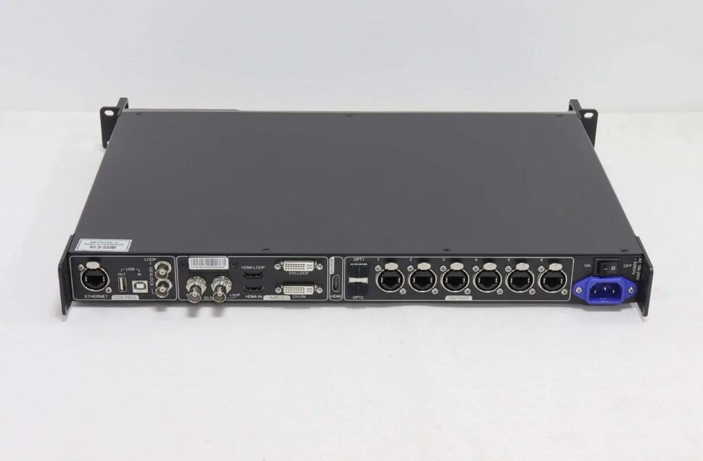
NovaStar Ethernet port backup provides an alternate LED data path when the supported hardware, cabling and redundancy settings have been configured together. It does not automatically protect against every controller, power, receiving-card or module failure. Define the failure you want to cover before counting spare ports or ordering another device.
This explanation is for an AV integrator specifying a rental display’s signal-path redundancy. It separates port backup from device backup, optical backup and stored configuration files. It is not a universal wiring or commissioning procedure for every NovaStar product.
The software reference is the NovaLCT synchronous-control manual V5.8.0, particularly its redundancy section. The hardware examples use the MCTRL660 PRO V1.0.0 and CVT10 V1.2.2 references. Available functions and verification tools depend on the actual connected models and programs.
What NovaStar Ethernet Port Backup Is Intended to Do
Port redundancy associates a primary output path with a defined backup path. A second connected cable is insufficient evidence that the association has been configured or that the receivers can use it as intended.
NovaLCT’s cited procedure identifies the sending-card serial numbers and output-port numbers for the primary and backup sides. It distinguishes a pair of ports within one sending card from redundancy between sending cards. Those identities matter because a physical port number alone does not identify the complete endpoint.
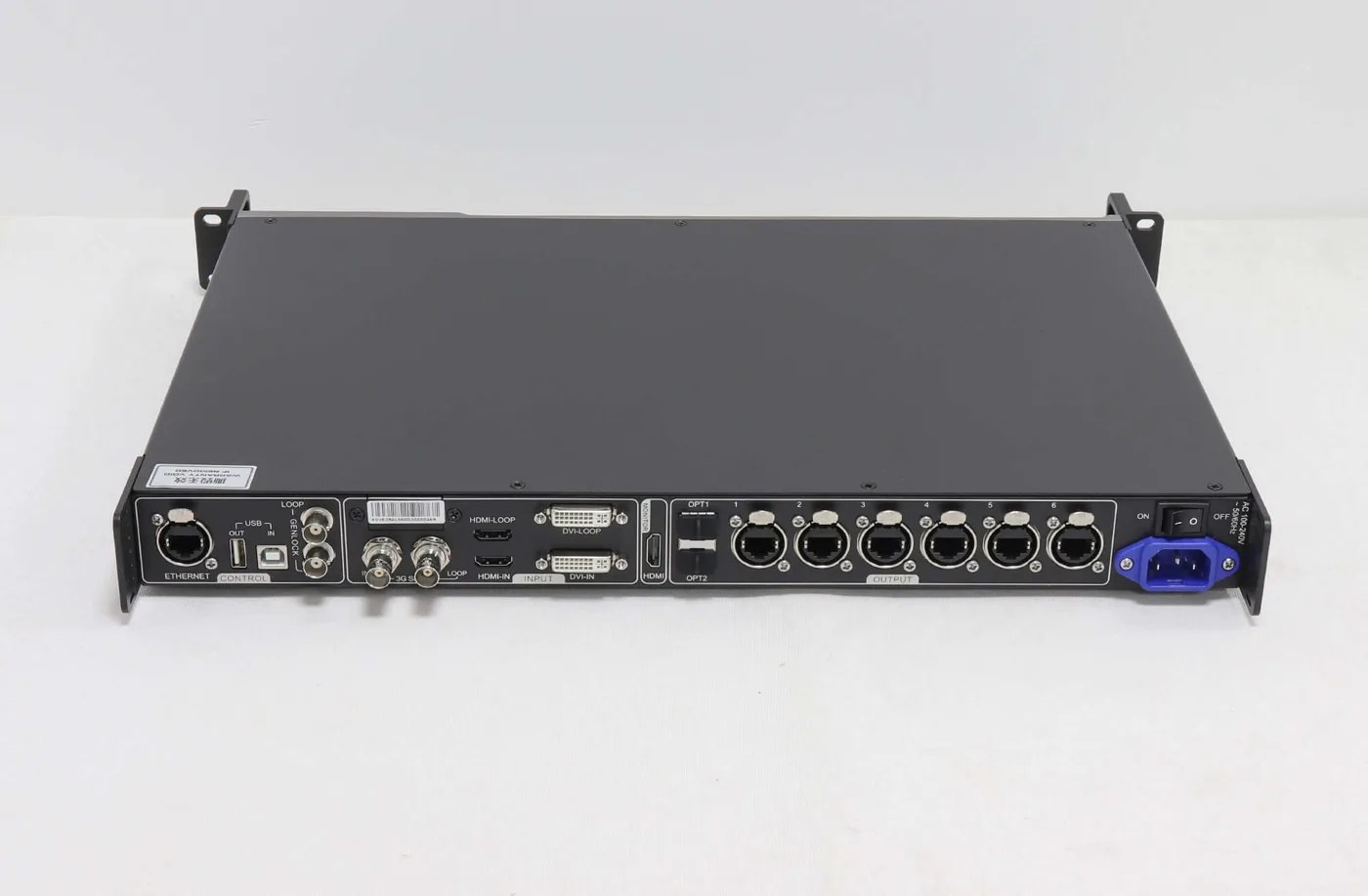
For NovaStar Ethernet port backup, draw the normal route and the alternate route on the same cabinet connection diagram. Label the sender, output port, cable path and receiver chain. A technician should be able to relate the drawing to the actual equipment without guessing which rear-panel socket is meant.
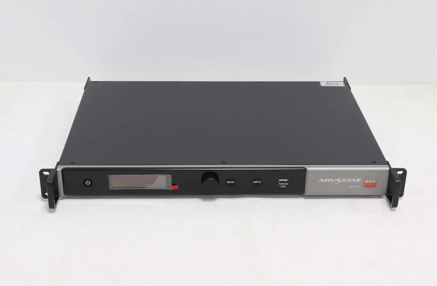
The MCTRL660 PRO product reference lists Ethernet-port redundancy. That feature is a reason to review its supported topology; it is not proof that an existing installation already has a working backup path.
Separate the Failure Paths Before Choosing Hardware
Different backup arrangements address different parts of the system. The table below is a planning framework: the actual coverage must be established by the supported design and an agreed acceptance test.
| Proposed arrangement | Path to investigate | Remaining question |
|---|---|---|
| Primary and backup ports on one sender | Alternate output and cable route for the defined receiver chain | What happens if that sender or its power supply becomes unavailable? |
| Backup path from another sender | Supported redundancy between identified sending devices | Are source, configuration, synchronization and power dependencies addressed? |
| Primary and backup optical connections | Alternate optical path under the device’s documented mode | Does the rest of the Ethernet and receiver path remain common? |
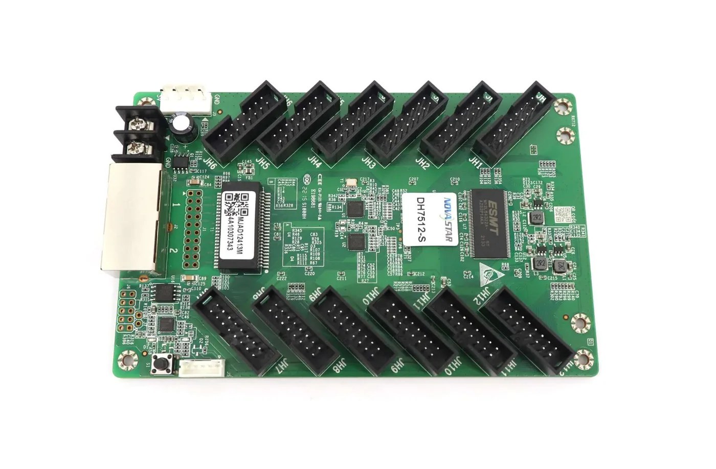
| Two receivers on a suitable hub assembly | Supported receiving-card backup arrangement | Which module, hub and power components are still shared? |
| Saved configuration files | Recovery information for service personnel | How will hardware failure be handled while a repair is performed? |
NovaStar Ethernet port backup should therefore be specified as coverage for an identified path, rather than described as “full redundancy.” If both data routes depend on the same device, a fault affecting that device remains a separate design question.
Physical routing also matters to the proposed coverage. Two cables sharing the same vulnerable route may be affected by one incident. Ask the project team which common dependencies are acceptable, then make those decisions visible in the drawing.
A second sender introduces other questions. It needs the intended source and an approved configuration. Do not assume that purchasing another controller, connecting a control cable or copying one file establishes every condition for a supported backup arrangement.
Keep Port Identity, Receiver Mapping and Settings Together
The cabling diagram and saved hardware settings must describe the same installation. A correct-looking software entry cannot validate a cable plugged into a different physical port.
For NovaStar Ethernet port backup within one sending card, the V5.8.0 manual uses the same sending-card serial identity for the primary and backup entries. Between sending cards, it uses the actual identities of the connected devices and requires the documented cascading arrangement before configuration.
This distinction is about identifying the intended endpoints. It is not a general instruction to enter matching numbers into every installation. Read the current equipment identities and use the procedure applicable to that system.
Record the receiver order and assigned cabinet areas with the port pairing. Where a wall contains different cabinet designs, make the relevant boundaries explicit. An alternate route that reaches receivers is still incomplete if it does not restore the intended image area and orientation.
Complete the applicable send and hardware-save operations, and retain an identified local backup. Saving a computer file and saving accepted settings to hardware serve different purposes. The RCFGX file explanation describes why the receiver profile is also separate from the overall screen connection record.
A Backup Port Is Not Another Independent Screen Area
A port assigned to protect an existing path should not also be assumed to provide an unrelated extra area. Calculate usable output allocation for the actual operating mode and redundancy design.
NovaStar Ethernet port backup does not multiply the sender’s advertised pixel capacity. Keep the normal image load, backup assignments and documented per-port conditions on the same planning sheet. Avoid adding every visible connector together as though each represented an independent display output.
The optical example makes this distinction clear. CVT10 V1.2.2 identifies OPT1 as primary and OPT2 as its backup in CVT mode. Those two connectors are not described there as two independent extra screen groups.
Likewise, reserve capacity according to the approved sender arrangement rather than using one universal percentage. Different hardware and operating modes can have different allocation rules. If the proposed design depends on a particular large-load or custom-program mode, obtain the matching documentation before making a capacity commitment.
Ask for a Failure-Specific Acceptance Record
A normal image proves normal operation at that moment. It does not demonstrate that the alternate path will work when the defined primary path becomes unavailable.
For NovaStar Ethernet port backup acceptance, agree on a controlled commissioning procedure with the responsible technician. Name the fault to be simulated, expected display behavior, recovery procedure and stopping conditions. Schedule testing so it does not create an unplanned interruption during a live event.
Retain the hardware identities, firmware and software versions, configuration reference and test result. State what was actually checked. A successful cable-path test should not be recorded as a power-failure test or as evidence that every component has a backup.
After service or a revised cabinet allocation, review whether the saved record still matches the installation. Changing a receiver chain or moving a cable to another output can affect the arrangement even when the main image appears normal.
Frequently Asked Questions
Does NovaLCT’s hot-backup verification tool apply to every sender?
No. The cited V5.8.0 manual specifically lists MCTRL4K, MCTRL R5 and KT8 for its hot-backup verification function. Do not assume the same tool or menu is available on MCTRL660 PRO or every other model.
Does keeping a spare receiving card provide automatic failover?
No. A boxed spare is a service part. An automatic receiving-card backup arrangement needs the supported receiver and hub-board design, appropriate configuration and acceptance testing.
Can a generic network switch be assumed to provide the backup route?
No. Use the documented LED data topology for the selected equipment. A familiar Ethernet connector does not establish support for an arbitrary network arrangement.
Does a successful NovaStar Ethernet port backup test prove that power is redundant?
No. It validates only the tested condition. Document power dependencies separately and have the responsible project team approve any required power-redundancy design.
Specify the Failure You Need to Cover
For a NovaStar Ethernet port backup inquiry, provide the sender model, output allocation, receiver-chain drawing, firmware information and required failure coverage. Review the sending-controller comparison and receiving-card options, then ask LED Mall to review the proposed hardware arrangement before ordering.