
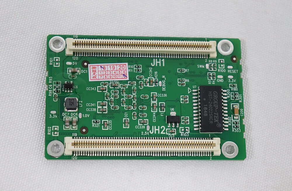
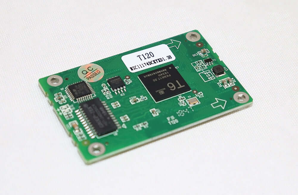
Mooncell T120 LED Receiving Card, 24 RGB Data Groups
$ 12.40
The Mooncell T120 receiving card supports 24 RGB data groups. Its linked V3.0 PDF lists 256 × 384 pixels maximum, with separate correction-mode limits; check the hardware revision because the original page differs on voltage and scan support.
10000 in stock
T120 receiving card: load modes and hardware revision
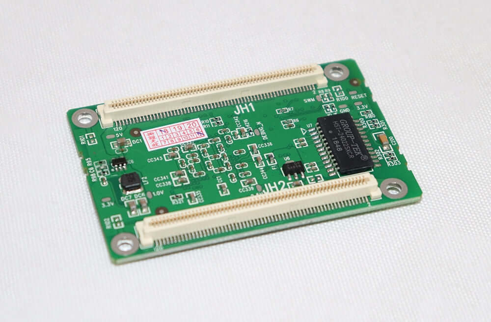
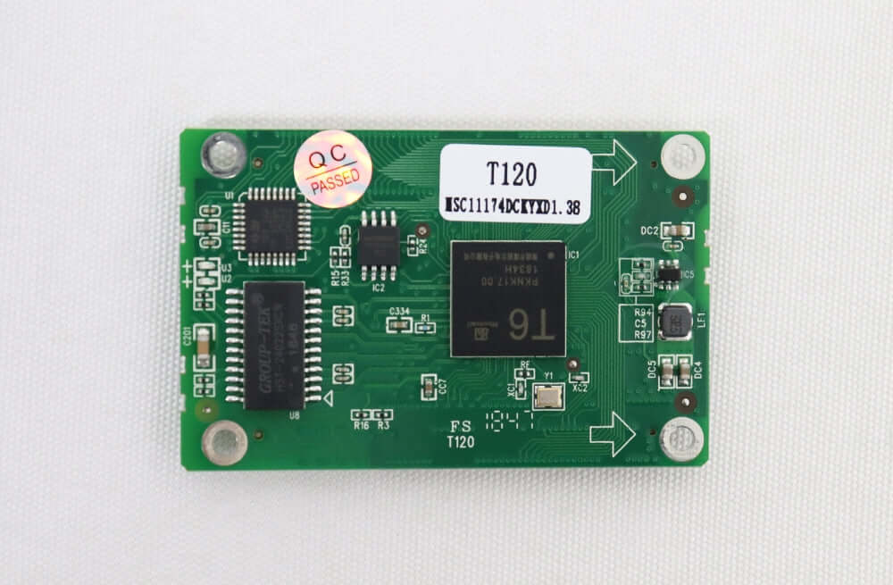
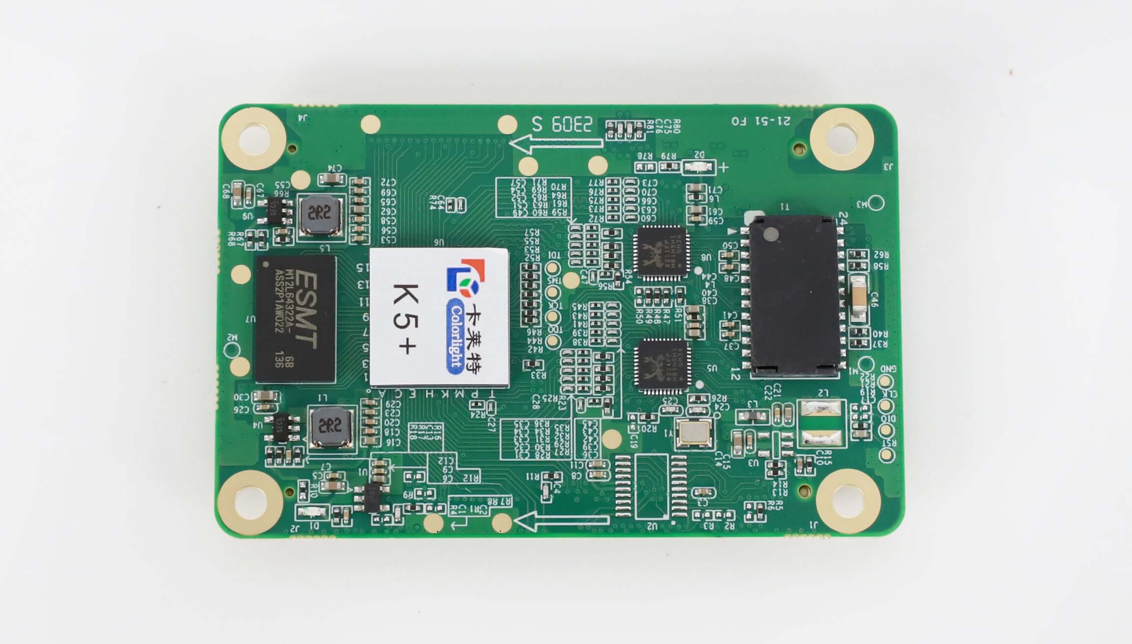
The Mooncell T120 is a compact LED receiving-card core board with 24 groups of RGB parallel data. The linked specification describes AutoLED configuration, pixel correction, rotation, scaling and network-port hot backup.
Match the document to the board: the linked T120 V3.0 specification identifies T120S V1.1 hardware in its revision record. Its voltage, scan and correction-load limits differ from the original product description. The table labels these differences rather than treating all revisions as having identical ratings.
Technical specifications
| Parameter | Specification |
|---|---|
| Model / document revision | Mooncell T120; linked document V3.0 identifies hardware T120S V1.1 |
| Parallel RGB data | 24 groups |
| Maximum load in V3.0 PDF | 256 × 384 pixels |
| Brightness / chromaticity correction load in PDF | 256 × 308 / 256 × 256 pixels |
| Original-listing load wording | Maximum 96K pixels; 8K per data group; the original no-load-loss correction claim differs from the PDF correction limits |
| Scan support — source difference | Original listing: 1–32 scan, including 595/serial decoding; V3.0 PDF: 1–64 scan |
| Input voltage — source difference | Original listing: +3.5 to +6 V; V3.0 PDF: DC 3.5–5.5 V |
| Rated current / power in PDF | 0.6 A / 3 W |
| Input / output grayscale in original listing | 8-bit or 10-bit input; up to 20-bit output |
| Configuration software in PDF | AutoLED |
| Display adjustment in PDF | Point brightness/chromaticity correction, 90°-increment rotation and scaling |
| Backup | Network-port hot backup; dual-power backup is identified as a customized option in the PDF |
| Maintenance in PDF | Parameter readback, hardware reset after online upgrade, cable bit-error detection and communication monitoring |
| Original-listing monitoring functions | Cabinet temperature, humidity, supply voltage and fans; ribbon-wire monitoring; external environment monitoring |
| Original-listing module functions | Intelligent-module parameter storage, position shifting, point fault detection and intelligent recovery after card exchange |
| Driver ICs in original listing | PWM, pixel-detection and conventional ICs |
| Working temperature / humidity in PDF | −20°C to +70°C / 10–90% RH |
| Board dimensions in PDF | 70 × 45 mm |
| Output connector documentation | JH1/JH2 definitions for 24-group parallel and 72-group serial data are included in the PDF |
Product images and specification download


Mooncell T120 High Standard Universal LED Screen Receiving Card Specification
Frequently asked questions
Does calibration reduce the T120 pixel load?
The original listing says correction does not reduce load, but the linked V3.0 PDF gives separate limits: 256 × 384 maximum, 256 × 308 with brightness correction and 256 × 256 with chromaticity correction. Confirm the hardware revision and use its matching correction-mode limits.
What supply voltage is specified for T120?
The original page states +3.5–6 V. The linked V3.0 PDF, whose revision record names T120S V1.1 hardware, states DC 3.5–5.5 V. Do not assume the higher voltage is approved for every T120 board revision.
Does every T120 include dual-power backup?
No such universal inclusion is established. The PDF labels dual-power backup as a customized feature. It separately describes network-port hot backup using main and standby cable paths.
Which software is listed for setup and diagnostics?
The linked PDF names AutoLED for configuration readback, cable bit-error monitoring, communication status, layout, rotation and scaling. Match the installed hardware and firmware to the appropriate software.
What does a green status light that is off indicate?
For the hardware documented in the linked PDF, the green U2 indicator being off means no Gigabit network signal. Slow flashing indicates a normal connection without DVI input; fast flashing indicates DVI input. Check the board revision before applying those indicator definitions.
| Weight | 0.2 kg |
|---|
Be the first to review “Mooncell T120 LED Receiving Card, 24 RGB Data Groups”
You must be logged in to post a review.
Will I be charged with customs and taxes?
The prices displayed on our site are tax-free (in US Dollars), which means you may be required to pay import duties and taxes once you receive your order. Import taxes, duties, and related customs fees will be determined by your local customs office when your order arrives at its final destination.
Please note that these additional charges and taxes are your responsibility, and we do not take any responsibility for them. We are not liable for paying or reimbursing any customs duties, taxes, or related fees. For more details on these charges, please contact your local customs office.
Shipping
We can ship to virtually any address in the world. Note that there are restrictions on some products, and some products cannot be shipped to international destinations..
When you place an order, we will estimate shipping and delivery dates for you based on the availability of your items and the shipping options you choose. Depending on the shipping provider you choose, shipping date estimates may appear on the shipping quotes page.
Please also note that the shipping rates for many items we sell are weight-based. The weight of any such item can be found on its detail page. To reflect the policies of the shipping companies we use, all weights will be rounded up to the next full pound..
Returns Policy
You may return most new, unopened items within 30 days of delivery for a full refund. We'll also pay the return shipping costs if the return is a result of our error (you received an incorrect or defective item, etc.)..
You should expect to receive your refund within four weeks of giving your package to the return shipper, however, in many cases you will receive a refund more quickly. This time period includes the transit time for us to receive your return from the shipper (5 to 10 business days), the time it takes us to process your return once we receive it (3 to 5 business days), and the time it takes your bank to process our refund request (5 to 10 business days).
If you need to return an item, simply login to your account, view the order using the "Complete Orders" link under the My Account menu and click the Return Item(s) button. We'll notify you via e-mail of your refund once we've received and processed the returned item..
Reviews
There are no reviews yet.