
LEDMall Blog
NovaStar MFN300 Light Sensor: What Automatic Dimming Needs
Nov
A NovaStar MFN300 light sensor connection is one part of an automatic LED brightness system. The MFN300 multifunction card provides four light-sensor connections, while the complete installation also needs a compatible sensor, a working communication path, supported control software, and a brightness policy suited to the site. Confirm those items together when requesting a quotation.
This explanation is for an AV integrator specifying automatic dimming for a fixed LED installation. It follows the manufacturer’s Multifunction Card MFN300 Specifications, Rev2.1.0, document NS110100087. The document identifies sensor connectivity and the card’s communication arrangements. It does not establish which sensor, cable length, or accessories a particular seller includes in a shipment.
What a NovaStar MFN300 light sensor connection provides
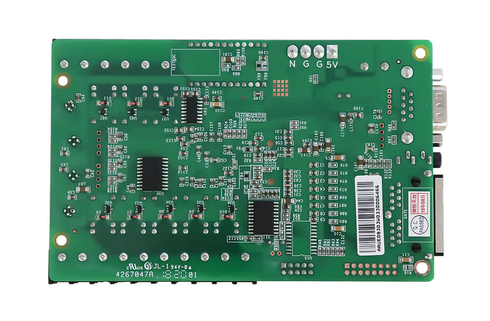
The MFN300 is a multifunction card that adds auxiliary control and sensing connections to an LED display system. Its published features include four-way light-sensor connection for automatic brightness adjustment, temperature and humidity functions, audio output, a timer, and eight-way power-switch control. Select the features the project actually needs and identify the equipment required for each.
The MFN300 product listing identifies the board and provides its retained specification. A receiving card has a different role in the system, handling the module-side display data. Adding an MFN300 addresses auxiliary functions. The module interfaces and loading capacity of the existing receiving cards still need to suit the screen.
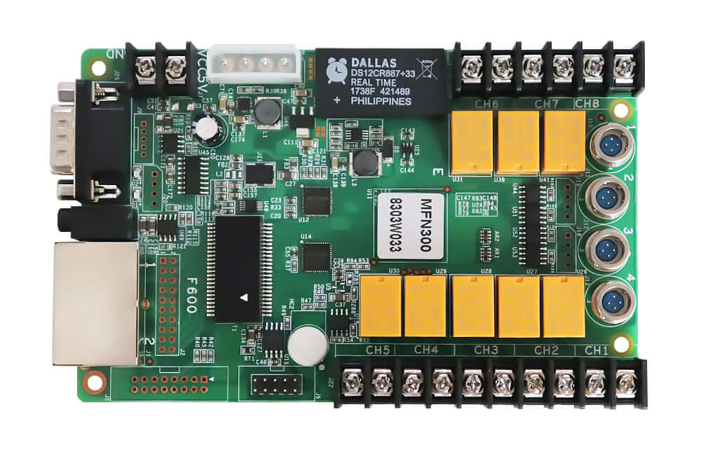
Four sensor connections describe connectivity on the card. They do not establish that four sensors are bundled with every order, or that every installation must use all four. Ask the supplier to identify the proposed sensor model, required quantity, connector arrangement, and included cables. List those items separately in the purchase documentation.
Follow the complete automatic-brightness chain
A NovaStar MFN300 light sensor arrangement needs a complete route from the measured light level to the display’s brightness setting. Review that route as a system requirement. A sensor can report a changing environment while an incorrect communication or software configuration prevents the intended brightness response.
Rev2.1.0 documents RS232 serial communication and Gigabit Ethernet communication. Its connection examples show a direct serial connection to a computer and Ethernet placements within the display control chain. For a retrofit, identify the actual sending controller, receiving cards, available connection points, and software used to manage the installation.
| System element | Information to confirm | Evidence to retain |
|---|---|---|
| Light sensor | Compatible model, quantity and supplied accessories | Model identification and accessory list |
| Communication | RS232 or Ethernet arrangement for the actual system | Controller model and connection diagram |
| Software | Supported version and responsibility for configuration | Recorded software version and agreed settings |
| Brightness policy | Required behavior under changing site illumination | Project acceptance criteria and operating limits |
The specification’s software section describes Function Card Management in NovaLCT-Mars. It covers adding and identifying a function card through its serial or Ethernet connection. Treat those screenshots as documentation for the described software generation. Confirm the supported workflow for the version in the installation before planning remote setup or a commissioning visit.
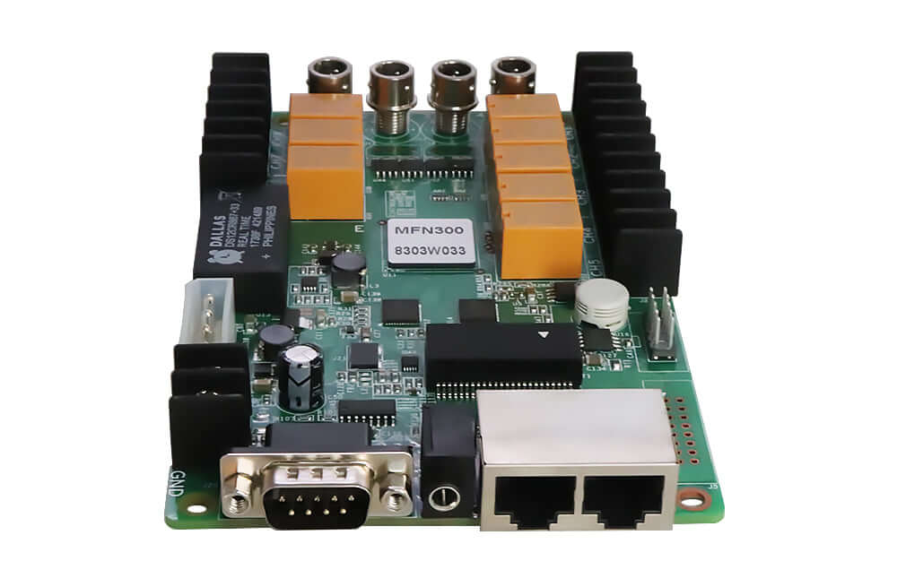
Document which computer or control system will configure and supervise the card. If an existing installation has no reliable equipment record, collect the controller and software details before ordering. A NovaStar MFN300 light sensor inquiry becomes easier to resolve when the supplier can evaluate a defined system instead of an unspecified “NovaStar screen.”
Define what the sensor should measure
Sensor position affects whether a light reading represents the conditions that matter to the display. Review the intended mounting point for shading, nearby lighting, reflections, and illumination from the LED screen itself. These are site-design questions to resolve with the integrator. The four-connection feature alone cannot determine a suitable mounting position.
For example, a sensor placed near a local light source may experience different conditions from the viewing area. This is a planning example, not a reported MFN300 test. Describe the proposed location, enclosure, cable route, and exposure to the supplier so the compatible sensor and installation requirements can be checked.
The NovaStar MFN300 light sensor system also needs an agreed brightness policy. Define the conditions under which brightness should change, the desired operating range, and any project-specific nighttime restrictions. Establish the policy with the screen operator and the person responsible for the site’s lighting requirements. Avoid assuming that a generic default will match every location.
Automatic adjustment does not establish the finished display’s calibrated brightness or guarantee compliance with a local requirement. Those outcomes depend on the screen, its settings, site conditions, and applicable project criteria. Keep the target behavior measurable so commissioning can verify what the installation actually does.
Verify the proposed arrangement before accepting it
Include sensor detection, communication, and the resulting brightness response in the sample acceptance plan. Record the sensor model, controller, card identification, software version, connection arrangement, and settings used. Check the response under the relevant changes in illumination and retain observations alongside the configuration record.
For a NovaStar MFN300 light sensor test, agree on the expected behavior before changing the environment. Record the conditions and whether the display reaches the intended setting. If the result differs, preserve that evidence for diagnosis. Changing the sensor location, software policy, and communication arrangement at the same time makes the cause harder to isolate.
Check the card’s own power and mounting requirements separately from the sensor function. Rev2.1.0 specifies DC 3.3–5.5 V input and dimensions of 144.0 × 94.8 × 20.0 mm, approximately 5.67 × 3.73 × 0.79 in. Have the responsible technician verify the supply and installation against the actual hardware documentation.
Keep the original operating configuration and an identified record of the accepted settings. The operator should know who maintains the policy and what to do if the sensor or communication path becomes unavailable. Agree on the required fallback behavior with the supplier and confirm it during commissioning, rather than assuming an undocumented default.
Check the full product designation on the quotation. The MFN300 board and a product labeled MFN300-B require their own documentation and accessory confirmation. A similar model name does not establish identical sensor connections, input power, enclosure, or installation requirements. Send a readable photograph of the existing item when requesting a replacement, especially if the original system documentation is incomplete.
The purchasing record for a NovaStar MFN300 light sensor system should identify who supplies the sensor, extension cable, mounting accessories, and any configuration service. If an item is excluded, make the responsibility explicit before installation begins. This prevents an apparently complete card order from leaving the installer without a necessary accessory or without an agreed way to validate the finished brightness response.
Frequently asked questions
Can I order the card first and choose any light sensor later?
Confirm the compatible sensor and connection requirements before committing to the order. Rev2.1.0 lists light-sensor connectivity, but that feature does not establish compatibility with an arbitrary sensor, connector, or extension cable.
Will the card’s temperature and humidity functions replace the light sensor?
They are separate environmental functions. The specification lists temperature and humidity functions alongside light-sensor connections. Specify the measurement required for each task and confirm the corresponding module or sensor with the supplier.
Does automatic dimming increase the receiving cards’ pixel capacity?
The documented MFN300 light-sensor function concerns brightness adjustment. Continue to assess the display-data hardware through the receiving-card specifications for the actual modules, source settings, and cabinet load.
Prepare the accessory inquiry
Send LED Mall the controller model, software version, proposed sensor location, cable route, quantity, and desired brightness behavior. Include photographs of the existing control equipment and explain whether the work is a retrofit or a new installation. Request a NovaStar MFN300 light sensor system review with an itemized accessory list and the compatibility points to confirm before purchase.