


NovaStar MRV210-2 Receiving Card | Connector & Pinout Guide
$ 18.00
Discontinued and no longer available. MRV210-2 is the MRV210 receiving-card variant with male connectors underneath. Review the revision-specific loading and pinout notes before servicing an existing cabinet.
Out of stock
MRV210-2 receiving card identification
This product is discontinued and no longer available. NovaStar’s MRV210 Rev2.1.2 model list identifies MRV210-2 as the variant with male connectors on the bottom. The family uses four 26-pin output interfaces with parallel or serial data modes.
| Parameter | Specification |
|---|---|
| Model / connector position | MRV210-2 / male connectors underneath, per Rev2.1.2 |
| Output interfaces | 4 × 26-pin |
| RGBR′ parallel mode | 16 groups |
| RGB parallel modes | 20 or 24 groups |
| Serial mode | 64 groups |
| 16-group scan support in V2.2.1 | 1/32 scan |
| 20-group scan support in V2.2.1 | 1/16 scan |
| 24-group scan support in V2.2.1 | 1/4 scan only |
| Input voltage in V2.2.1 | DC 3.3–5.5 V |
| Rated current / power in V2.2.1 | 0.5 A / 2.5 W |
Loading and wiring differences between sources
The original listing states 256 × 220 pixels. MRV210 Rev2.1.2 states 256 × 226, while the attached MRV210 V2.2.1 specification states 256 × 256. These are revision-dependent source values; the general MRV210 PDF does not establish that every older MRV210-2 board has the later loading capability.
The earlier page also claimed expansion from 64 to 128 serial groups. Neither reviewed manufacturer revision confirms that expansion. Check the exact hardware, firmware and output-mode pinout rather than assuming 128-group support.
VCC pin: V2.2.1 identifies pin 6 as a reserved 3.3 V output with a maximum output current of 50 mA. This differs from the earlier page’s suggestion that modules can supply the control system through VCC. Do not treat this reserved pin as the board’s power-input connector; verify the applicable revision’s wiring.
Maintenance functions
The MRV210 documentation supports configuration readback, temperature and voltage monitoring, pixel-level brightness and chroma calibration and a pre-stored image. V2.2.1 also describes cabinet LCD monitoring, loop backup, dual application-program backup and 3D with a compatible sending card. Match feature availability to the installed revision.
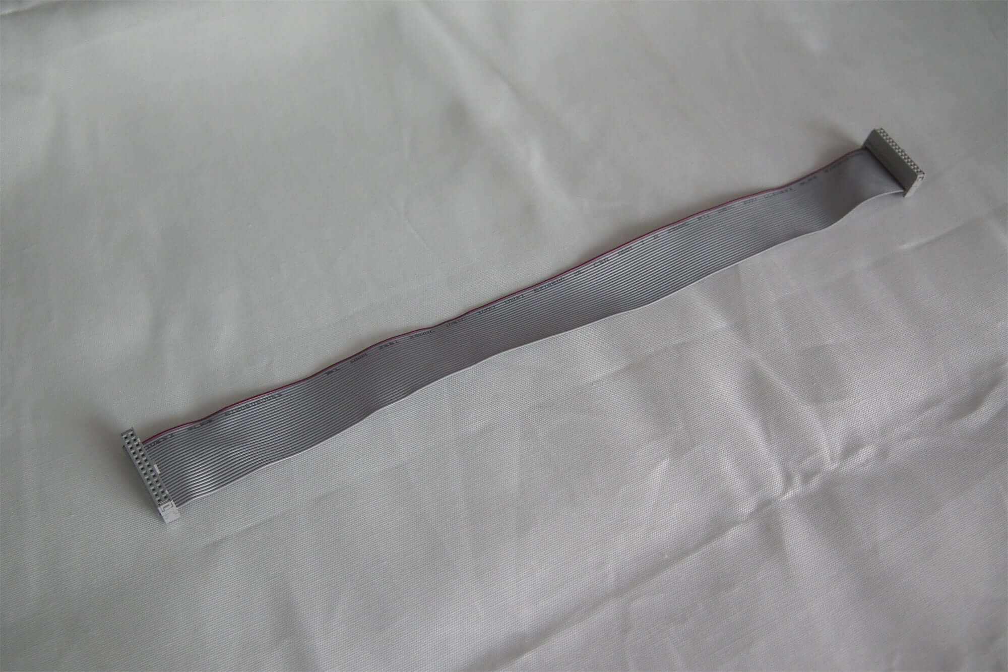
Original product images


Download specification
MRV210 family receiving card specifications — V2.2.1 (PDF)
The original link label referred to MRV210-1, but the file itself is titled MRV210. It is retained as family documentation; confirm the MRV210-2 connector arrangement separately.
Frequently Asked Questions
What is the difference between MRV210-1 and MRV210-2?
Rev2.1.2 identifies MRV210-1 as the male-connector-on-top variant and MRV210-2 as the male-connector-on-bottom variant. Check the board label and physical orientation together.
Is the MRV210-2 still available?
No. This product listing states that it is discontinued and no longer available.
Which loading value applies: 256 × 220, 256 × 226 or 256 × 256?
The old listing states 256 × 220, manufacturer Rev2.1.2 states 256 × 226, and V2.2.1 states 256 × 256. Confirm the installed MRV210-2 revision and firmware; do not apply a later family specification automatically to an older board.
Can the VCC pin be used to power the receiving card?
The linked V2.2.1 pinout defines pin 6 as a reserved 3.3 V output limited to 50 mA, not the board power input. Verify the correct power connector and the pinout for the actual board revision.
Does 24-group RGB mode support every scan setting?
No. V2.2.1 specifies 1/4 scan only for the 24-group mode. It documents 1/32 scan for 16-group RGBR′ mode and 1/16 scan for 20-group RGB mode. Use the pinout corresponding to the selected mode.
| Weight | 0.3 kg |
|---|
Be the first to review “NovaStar MRV210-2 Receiving Card | Connector & Pinout Guide”
You must be logged in to post a review.
Will I be charged with customs and taxes?
The prices displayed on our site are tax-free (in US Dollars), which means you may be required to pay import duties and taxes once you receive your order. Import taxes, duties, and related customs fees will be determined by your local customs office when your order arrives at its final destination.
Please note that these additional charges and taxes are your responsibility, and we do not take any responsibility for them. We are not liable for paying or reimbursing any customs duties, taxes, or related fees. For more details on these charges, please contact your local customs office.
Shipping
We can ship to virtually any address in the world. Note that there are restrictions on some products, and some products cannot be shipped to international destinations..
When you place an order, we will estimate shipping and delivery dates for you based on the availability of your items and the shipping options you choose. Depending on the shipping provider you choose, shipping date estimates may appear on the shipping quotes page.
Please also note that the shipping rates for many items we sell are weight-based. The weight of any such item can be found on its detail page. To reflect the policies of the shipping companies we use, all weights will be rounded up to the next full pound..
Returns Policy
You may return most new, unopened items within 30 days of delivery for a full refund. We'll also pay the return shipping costs if the return is a result of our error (you received an incorrect or defective item, etc.)..
You should expect to receive your refund within four weeks of giving your package to the return shipper, however, in many cases you will receive a refund more quickly. This time period includes the transit time for us to receive your return from the shipper (5 to 10 business days), the time it takes us to process your return once we receive it (3 to 5 business days), and the time it takes your bank to process our refund request (5 to 10 business days).
If you need to return an item, simply login to your account, view the order using the "Complete Orders" link under the My Account menu and click the Return Item(s) button. We'll notify you via e-mail of your refund once we've received and processed the returned item..
Related products




Reviews
There are no reviews yet.