
Ιστολόγιο LEDMall
J6 DVI Outputs: Why Eight Sockets Are Not Eight Screens
Νοέμβριος
J6 DVI outputs are organized into four groups, each with a main and a backup connector. Eight physical DVI sockets therefore do not mean eight independent screen outputs. The usable groups also change with the Splicer or Switcher system mode and the single-link or dual-link output setting.
This explanation is for a rental-equipment buyer approving the output map for a show. It uses NovaStar J6 Specifications V2.2.0 and section 4.3.1 of J6 User Manual V3.1.0. Those are document versions, not a claim about the firmware fitted to an offered unit. Confirm that unit’s hardware and firmware before approving the final connection plan.

Count J6 DVI outputs by function
The manufacturer’s specification describes four output groups with two connectors per group: main and backup. Count the groups when discussing the screen plan, then identify the physical connector required for each cable. Do not turn the backup member of a pair into another canvas area on the purchasing drawing.
A useful equipment schedule has separate columns for connector group, cable label, destination and purpose. This prevents an inventory count from becoming a promise about independent pictures. It also gives the technician something definite to inspect when the quoted unit arrives at the warehouse.
For example, a request for “eight DVI cables from the processor” leaves the actual requirement unclear. Ask whether the buyer needs separate screen regions, duplicate paths or monitor feeds. These requirements cannot be treated as interchangeable simply because they all use cables with the same connector shape.
Define what the buyer means by a screen as well. One large LED canvas may contain many cabinets, while two physical displays might be intended to show one continuous picture. Neither the cabinet count nor the room count supplies the output map. When discussing J6 DVI outputs, mark logical image regions on the drawing and state whether they should share content or serve different purposes. This gives the supplier a defined display requirement instead of a number that can be interpreted several ways.
Χρησιμοποιήστε το NovaStar J6 product listing to identify the equipment being quoted. Its published product information references an older specification revision as well. Keep the document revision attached to each technical claim; do not combine older and newer maximum figures into a capability that neither document promises.
Which groups remain available in each mode?
The following J6 DVI outputs table follows the detailed Output Mode section of User Manual V3.1.0. SL means single link; DL means dual link. Read the output setting and system mode together before assigning a destination.
| System / output mode | Documented output groups | Σημαντικό όριο |
|---|---|---|
| Splicer / SL | DVI 1, 2, 3 and 4 | Four groups for the output map, not eight independent socket feeds. |
| Splicer / DL | DVI 1 and 3 | DVI 2 and 4 are unavailable. |
| Switcher / SL | DVI 1 and 2 | DVI 3 and 4 are unavailable in this mode description. |
| Switcher / DL | DVI 1; DVI 3 assigned to AUX | DVI 2 and 4 are unavailable; AUX is not an additional program mosaic area. |
There is a documentation caution around AUX: the manual’s connector overview and its detailed mode section do not use identical mode wording. This table follows section 4.3.1, which agrees with the specification’s Switcher-mode AUX description. Ask the supplier to confirm the required AUX behavior on the offered firmware before relying on it in a show plan.
For J6 DVI outputs, changing to DL is therefore more than a choice about one cable. It changes the available group map. If an existing drawing uses a group that the selected mode makes unavailable, resolve that conflict before ordering; adding another cable does not resolve the mode restriction.
Name the equipment at the other end
Review J6 DVI outputs with the downstream destination attached to every group. A processor’s output role, a downstream device’s accepted input timing and the LED cabinet arrangement are separate requirements. A connector map alone does not certify the complete signal path.
Start with the actual receiving device model and its documented input requirements. Then record the intended timing and cable path. If an adapter or intermediate device is necessary, identify it explicitly in the quotation rather than treating it as a small accessory that can be selected later.
The J6 specification separately identifies HDMI MONITOR for viewing sources, preview and program. A monitoring function should not silently become another audience-screen output on the layout. Put operator monitoring on its own line so it cannot be confused with the required program-screen arrangement.
For LED installations, identify the sending stage after the video processor. The product page documents J6’s RJ45 connection as a control interface; its presence is not evidence of a direct LED receiving-card output. Browse the Κατηγορία κουτιού αποστολής LED when identifying downstream equipment, then verify the particular device’s input compatibility.
Do not infer that a single-link-to-dual-link cable change makes the downstream device compatible. Treat link mode as part of the signal requirement. Ask for written confirmation of the complete path and a demonstration with the intended equipment where the project depends on that combination.
Approve the show state before the cable count
A J6 DVI outputs review should start with the hardest required show state: which audience areas must display a picture simultaneously, and which operator feeds must also remain available? Identify those destinations before choosing a system mode or counting spare cables.
- Separate program and monitoring: mark every audience destination, operator display and proposed AUX use.
- Record both mode choices: list system mode and SL/DL output mode beside the drawing.
- Assign the groups: label each required destination with the documented group and physical cable endpoint.
- Verify the signal: attach each destination’s accepted timing and the intended connection hardware.
- Keep the acceptance evidence: record the actual unit, firmware and accepted picture arrangement for handover.
Use identifiable content during the review. Label the intended regions and check that each appears at the expected destination. A correct picture on one monitor is not evidence that the entire show map is correct. Have the person responsible for the production requirement approve any reduction in independent screen areas.
If a later show needs a different mode, treat the revised J6 DVI outputs drawing as a new configuration to review. Keep the previously accepted settings available for recovery. This is more useful than a generic instruction to use “the same controller,” because the physical chassis can remain unchanged while its available group roles change.

Remaining questions about J6 DVI outputs
Does the word backup establish complete system redundancy?
No. The connector-pair description does not by itself establish protection against every processor, source, power or downstream failure. Define the failure you need to tolerate and request a separate redundancy design and acceptance test.
Can a product photograph establish the supplied input configuration?
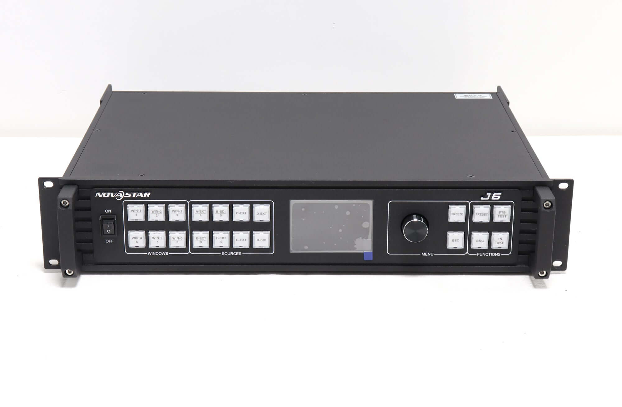
No. Use it to identify visible labels, then obtain the configuration of the actual quoted unit. This matters when a supplier offers selectable input options or a unit from a different hardware revision.
What should a quotation say if the operating mode is undecided?
State the required destinations and mark mode selection as unresolved. Do not approve a final cable and output allocation until the supplier has confirmed a compatible configuration for those requirements.
Review J6 DVI outputs against your show drawing
Send the audience-screen layout, monitoring and AUX requirements, downstream device models, proposed timings and desired system mode. Include a rear-panel photograph and firmware details for an existing unit. These inputs make the output-map discussion specific enough to resolve before purchase.
Request a J6 output-map and equipment review. Ask the quotation to identify the supplied configuration and any unresolved compatibility conditions.