
Блог LEDMall
Как проверить надежность и стабильность светового потока светодиодных чипов
окт
To test an LED display chip, measure its light output, color and forward voltage before and after a controlled aging run. Use the same measurement current, temperature and optical setup for both readings. Compare each LED with its own starting values and record any devices that went dark or became intermittent.
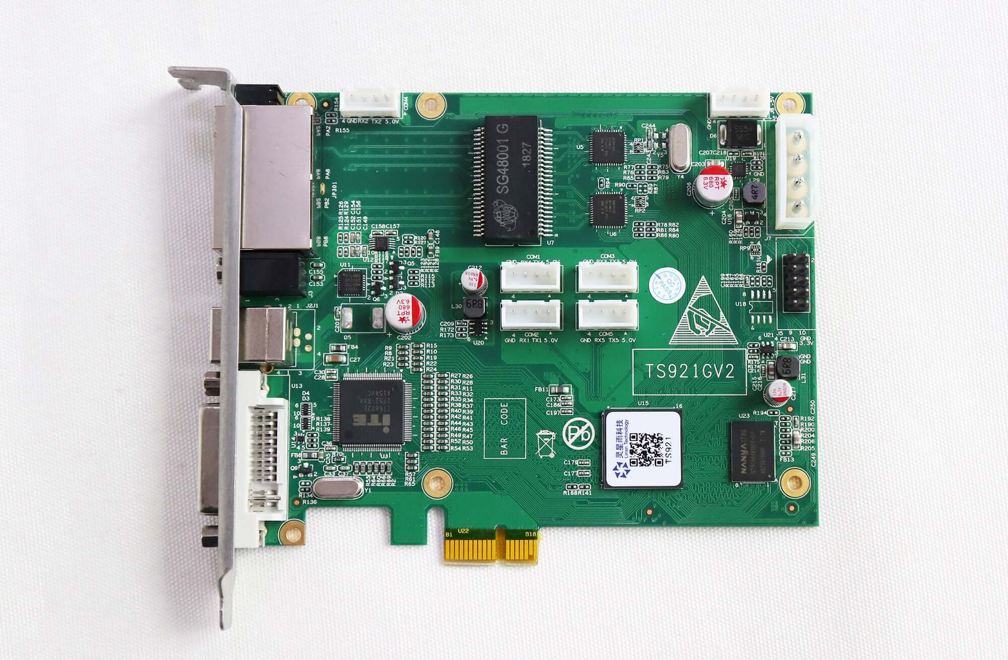
In this guide, “chip” means the light-emitting die in a display pixel. A supplier may test the bare die or the packaged LED that goes onto the module. Ask which one was tested. A package test also captures changes in its optical material, internal connections and thermal path.
1. Set the LED Life Test Conditions
(1) Define a pass before powering the samples
A pixel can still light up after aging and fail a color or brightness requirement. Define stability in terms you can measure, such as the allowable change in luminous intensity or color coordinates. For reliability, specify what counts as a failure and the operating period over which each sample must meet the requirements.
(2) Specify the electrical and thermal conditions
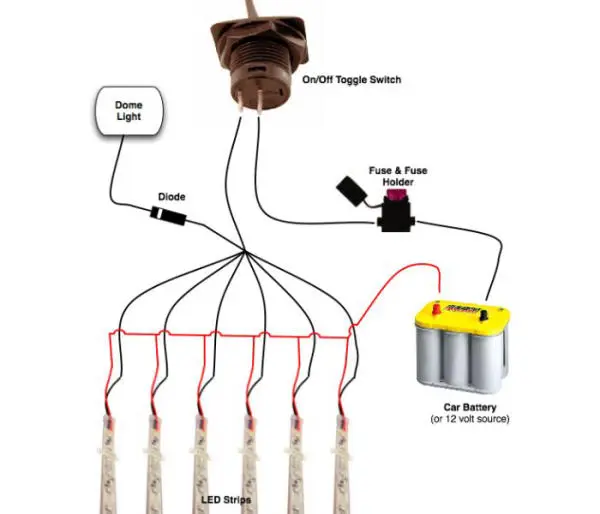
Use the datasheet for the exact part and color channel. For a scanned display, record peak current, pulse width and duty cycle. Two drive patterns can have the same average current but expose the LED to different peak currents. For temperature, identify the sensor location so that someone repeating the test knows which temperature to reproduce.
| Тестовый предмет | Что нужно указать | Как это интерпретировать |
|---|---|---|
| Идентификатор образца | Модель светодиода, цвет, тип корпуса, тип пластины или производственной партии, количество образцов и метод отбора. | Результаты относятся к выборке населения в условиях, описанных в документации. |
| Электрическое напряжение | Прямой ток, режим управления и, для импульсного режима работы, пиковый ток, ширина импульса и коэффициент заполнения. | Используйте параметры, специфичные для данной модели; средний ток сам по себе не описывает импульсное напряжение. |
| Тепловые условия | Температура окружающей среды, способ крепления, воздушный поток и точка измерения температуры. | Температура окружающей среды не является температурой перехода светодиода. |
| Продолжительность теста | Прошедшее время работы, интервалы измерений и любые перебои. | Кратковременный скрининговый период не является подтвержденным прогнозом продолжительности жизни. |
| Критерии принятия | Допустимые изменения оптических характеристик, дрейф электрических параметров и функциональные сбои были согласованы до начала испытаний. | Используйте соответствующую спецификацию продукта или план квалификации; универсального порогового значения для прохождения проверки не существует. |
(3) Choose a duration that answers the test question
A burn-in run can reveal early failures. A qualification test asks whether a defined sample meets agreed limits after a specified exposure. If a supplier quotes a projected lifetime, ask for the measured hours, the performance endpoint and the method used to extrapolate from the measurements.
2. Measure LED Performance Before and After Aging
(1) Select and identify the samples
For an incoming shipment, select devices from the production lots you intend to accept. For a wafer study, record where on the wafer each die came from. Give every sample a fixture position and an ID. Record any defects found at inspection, even if only initially conforming devices will enter the aging run.
(2) Measure light output, color and forward voltage
Take baseline readings, repeat them at the planned intervals, and let the devices settle at the specified measurement temperature each time. For an RGB package, record red, green and blue separately. A white pixel can change tint when one channel loses output faster than the other two.
If you measure luminous intensity in candelas, fix the viewing angle and distance. A small tilt can change the reading for a narrow-beam LED. If you measure total luminous flux in lumens, use flux again for the final reading. The two quantities describe different aspects of the emitted light.
| Измерения | Запись | Правило сравнения |
|---|---|---|
| Оптический выход | Начальный и последующий световой поток, или интенсивность свечения под фиксированным углом. | Используйте одинаковую оптическую величину и геометрию измерения на всех этапах. |
| Прямое напряжение | Напряжение при заданном токе измерения и температуре. | Сравните каждый образец с его собственным базовым уровнем; исследуйте неожиданные отклонения. |
| Однородность цвета | Цветовые координаты или доминирующая длина волны, если это применимо к типу светодиода. | Используйте те же настройки прибора и согласованные цветовые пределы. |
| Функциональные сбои | Обрыв цепи, короткое замыкание, прерывистый выходной сигнал и время обнаружения. | В отчете следует оставлять неудачные образцы, а не усреднять только успешные. |
| Условия испытаний | Текущий ток, температура, перебои в работе, идентификатор прибора и состояние калибровки. | Отделите изменения в креплении или методах измерения от фактического износа устройства. |
Light output retention (%) = final output ÷ initial output × 100. For example, an LED that measured 10.0 mcd initially and 9.2 mcd after aging retained 92% of its initial intensity. Report the measurement interval alongside that figure. List failed devices separately so a strong average among survivors cannot hide a failure.
(3) Check the package when output falls
When light output drops, first repeat the reading at the original alignment and temperature. Then examine the package for discoloration or other visible changes. An encapsulant that transmits less light can lower the reading even while the die emits light. Record any sunlight or ultraviolet exposure if the samples were evaluated for outdoor service.
(4) Investigate assembly-related failures
Group unusual results by lot and fixture position. If several outliers occupy one part of the bench, check the local temperature and channel current before attributing the pattern to the LEDs. Keep failed parts for inspection. Die attachment, wire bonds and mounting can each affect the result, and some defects require analysis beyond a visual inspection.
3. Set Up and Check the LED Life Test Bench
(1) Verify the current in each branch
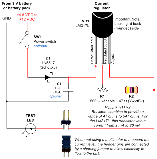
LEDs connected in series carry the same current. Parallel strings can draw different currents because their forward voltages differ. Use branch current regulation or a verified balancing circuit, then measure each branch with the fixture populated. Check that the supply can cover the combined forward voltage of a string plus the voltage its current regulator needs.
For the LM317 circuit shown above, check the regulator’s voltage headroom and heat dissipation at the intended string current. Select component values for the LED under test.
(2) Trace a dark string to the failed position
One open connection can extinguish a whole series string. Check the supply and fixture connections, then isolate the suspect device. With a shorted LED, one position can stay dark while current still flows through the others. Record which sample failed and how long its neighbors were without current.
(3) Review the bench log and supplier report
Use powered hours from the log. A fixture shut down for a weekend adds elapsed time without adding operating exposure. Check the sample IDs against the report and look for missing final readings, substitutions or exclusions before accepting the reported pass count.
Светодиоды Cree Обзор надежности светодиодов XLamp lists different test conditions and failure criteria for different product groups. Its Long-Term Lumen Maintenance document distinguishes measured output from projected maintenance life. For a display pixel, use the qualification plan for that pixel’s own part number.
Для проверки параметров дисплея ознакомьтесь с нашим руководством по измерению и проверке яркости светодиодных дисплеев.
4. Часто задаваемые вопросы
(1) Can I test an LED display chip with a multimeter?
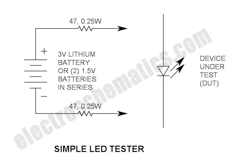
A meter in diode-test mode can help check polarity and forward conduction if its test voltage is sufficient for the LED. Some meters cannot light a blue or green LED. A single reading gives no measurement of light loss or color drift over time.
(2) What does a 96-hour LED burn-in test prove?
It tells you how the tested samples behaved during those 96 hours at the stated current and temperature. If a report says only “passed,” ask how many LEDs entered the test, how many failed and whether light output was measured. Those details determine what the result supports.
(3) What current should I use for an RGB display LED?
Identify the part number, the color channel and whether the test uses continuous or pulsed drive. Use a test point supported by the datasheet and qualification plan. A peak pulse rating applies only under its stated pulse conditions.
(4) Why does an LED look dimmer after it warms up?
Light output can change with junction temperature. Allow the device to return to the baseline measurement conditions and remeasure it at the same current. Any remaining difference warrants checking the optical setup and the sample for lasting changes.
(5) Does a passing LED chip test cover the whole screen?
No. Module solder joints, driver electronics, power distribution and cooling introduce other failure points. Check the assembled screen under its intended scan and brightness settings, including solid red, green and blue patterns to reveal missing or uneven pixels.
5. Заключение
A useful reliability report lets you follow one LED from its first reading to its last. Look for its part and lot, drive conditions, powered hours, initial and final optical readings, and any recorded failure. If a supplier gives only a lifetime figure or an average brightness value, ask for the underlying sample results before using that figure to qualify a display module.