
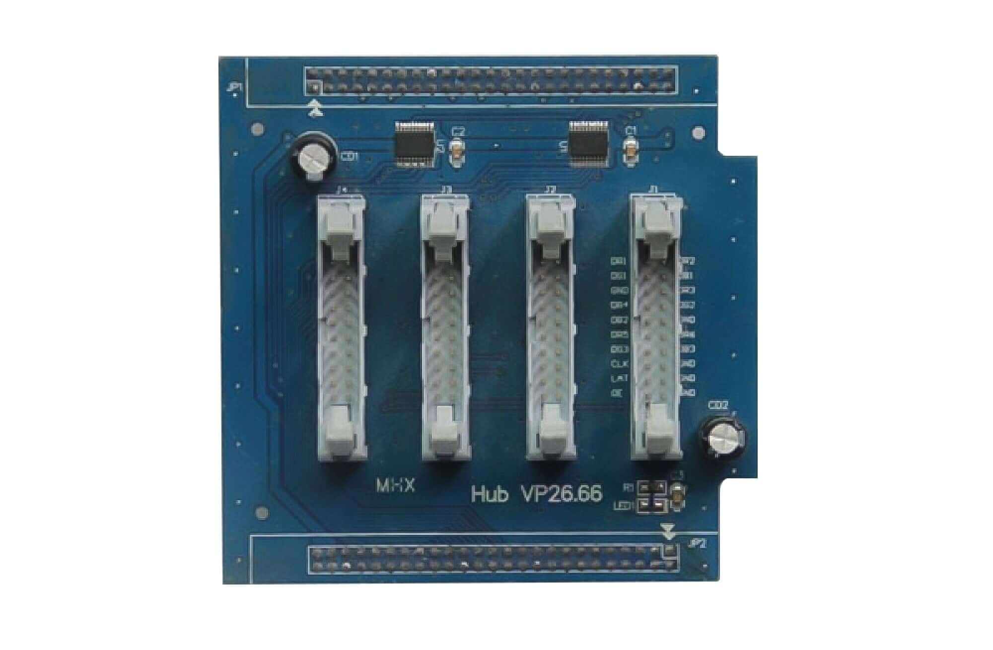
HUBvP26.66 20-Pin LED Display HUB Card
$ 12.00
HUBvP26.66 is an LED signal transfer card with a 20-pin interface. The numbered table identifies each connection for comparison with the mating module.
Use the pin-one mark to orient the connector. The map begins with RD1 and RD2 on pins 1 and 2. Data labels in this definition run from RD1 on pin 1 to BD3 on pin 14.
Connector pin assignments
| Pin | Signal | Pin | Signal |
|---|---|---|---|
1 | RD1 | 2 | RD2 |
3 | GD1 | 4 | BD2 |
5 | GND | 6 | RD3 |
7 | RD4 | 8 | GD2 |
9 | BD2 | 10 | GND |
11 | RD5 | 12 | RD6 |
13 | GD3 | 14 | BD3 |
15 | CLK | 16 | GND |
17 | LAT | 18 | GND |
19 | OE | 20 | GND |
Frequently asked questions
Where are the control signals on HUBvP26.66?
CLK on pin 15, LAT on pin 17, OE on pin 19. Match these labels against the mating connector before installing the board.
Which positions are marked ground?
The interface definition marks 5, 10, 16, 18, 20 as GND. Check the connector orientation before counting pin positions.
Why does BD2 appear more than once?
The published interface map uses BD2 at pins 4 and 9. Confirm those positions against the board markings before wiring.
| Weight | 0.2 kg |
|---|
Be the first to review “HUBvP26.66 20-Pin LED Display HUB Card”
You must be logged in to post a review.
Will I be charged with customs and taxes?
The prices displayed on our site are tax-free (in US Dollars), which means you may be required to pay import duties and taxes once you receive your order. Import taxes, duties, and related customs fees will be determined by your local customs office when your order arrives at its final destination.
Please note that these additional charges and taxes are your responsibility, and we do not take any responsibility for them. We are not liable for paying or reimbursing any customs duties, taxes, or related fees. For more details on these charges, please contact your local customs office.
Shipping
We can ship to virtually any address in the world. Note that there are restrictions on some products, and some products cannot be shipped to international destinations..
When you place an order, we will estimate shipping and delivery dates for you based on the availability of your items and the shipping options you choose. Depending on the shipping provider you choose, shipping date estimates may appear on the shipping quotes page.
Please also note that the shipping rates for many items we sell are weight-based. The weight of any such item can be found on its detail page. To reflect the policies of the shipping companies we use, all weights will be rounded up to the next full pound..
Returns Policy
You may return most new, unopened items within 30 days of delivery for a full refund. We'll also pay the return shipping costs if the return is a result of our error (you received an incorrect or defective item, etc.)..
You should expect to receive your refund within four weeks of giving your package to the return shipper, however, in many cases you will receive a refund more quickly. This time period includes the transit time for us to receive your return from the shipper (5 to 10 business days), the time it takes us to process your return once we receive it (3 to 5 business days), and the time it takes your bank to process our refund request (5 to 10 business days).
If you need to return an item, simply login to your account, view the order using the "Complete Orders" link under the My Account menu and click the Return Item(s) button. We'll notify you via e-mail of your refund once we've received and processed the returned item..
Related products
Reviews
There are no reviews yet.